


Operating Manual
Installation
PN 8500-0150, Rev. A, May 2005 4
The 5401 is now operational and will begin to discipline the Rubidium using the control
parameters that were previously stored in battery-backed RAM when the unit was last
powered-down.
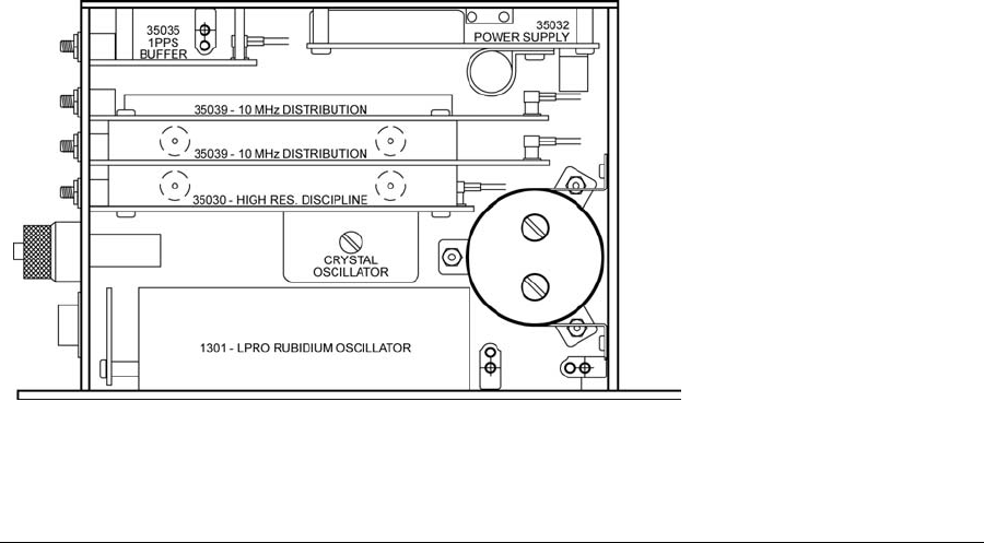
Symmetricom 5401 Adjustments
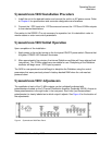
The amplitude of each of the 10 MHz outputs can be individually adjusted with
potentiometers located on the 3-Channel Distribution Amplifier (Assembly 35039).
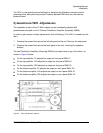
In order to gain access to these adjustments, do the following: (The 5401 is viewed from the
rear.)
1. Remove the screws that secure the left side panel to the unit. Remove the side panel.
2. Remove the screws that secure the back panel to the unit, including the capacitor
bracket.
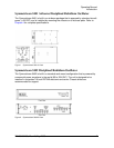
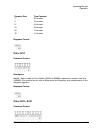
The two Distribution Amplifiers (Assembly 35039) are located one on top of the other, as
shown in Figure 3 below.
On the top amplifier, R1 adjusts the output on front panel SMA J7.
On the top amplifier, R18 adjusts the output on front panel SMA J8.
On the top amplifier, R22 adjusts the output on front panel SMA J9.
On the bottom amplifier, R1 adjusts the output on front panel SMA J10.
On the bottom amplifier, R18 adjusts the output on front panel SMA J11.
On the bottom amplifier, R22 adjusts the output on front panel SMA J12.
Figure 3 5401 Adjustment Locations