


RCC130H-CRACK SAW OPERATION AND PARTS MANUAL REV #1 (11/18/04) PAGE 33
MAINTENANCE/SERVICE
CAUTION
Observe all applicable safety precautions for the
solvent.
3) Remove the belt guard from the main frame.
Clean the inside of the belt guard with an
appropriate solvent. Check for signs of wear and
damage. Secure in a proper storage area.
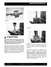
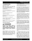
4) Using the 9/16 inch wrenches, loosen the
engine/motor mounting capscrews.
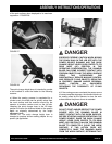
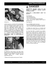
5) With the same wrenches, rotate the engine take-
up capscrews counterclockwise to loosen the V-
belts and allow the engine/electric motor to slide
toward the operator handle. FIGURE 37.
6) Remove the worn V-belts. Inspect the
engine/electric motor and arbor shaft pulleys for
wear and damage. Install the replacement belts, PN
BX34 in pairs. The Crack Saw utilizes two V-belts.
Always install replacement belts in matched pairs.
Never replace just one of the V-belts.
CAUTION
Do not operate the Crack Saw with only one V-
belt installed. One V-belt is not capable of
transmitting proper horsepower and torque
levels to the arbor shaft.
a) Do not install replacement belts if the pulleys
have excessively worn grooves. Such pulleys should
be replaced to insure proper belt fit. Operating the V-
belts in worn pulley grooves will accelerate wear,
reduce horsepower and torque levels and
significantly reduce component service life.
b) A V-belt should never be forced over a pulley.
More belts are broken from this cause than from
actual failure in service.
c) Keep the belts as clean and free of foreign
material as possible. Do not use belt dressing.
FIGURE 37
7) Tighten the engine/electric motor attachment
capscrews until they just begin to apply tension to
the engine/electric motor. DO NOT OVER
TIGHTEN. Alternately tighten the take-up capscrews
until slight tension is applied to the V-belt.
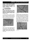
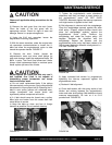
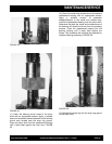
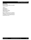
8) Belt alignment is checked with the straightedge.
Place the straightedge squarely against the arbor
shaft pulley. Properly aligned pulleys should also
place the straightedge squarely against the
engine/electric motor pulley. Remove the
straightedge and rotate the engine pulley 120
degrees. Recheck the alignment with the
straightedge. Repeat the process until the
engine/electric motor pulley has been rotated a full
360 degrees. Maximum allowable misalignment is +-
1/32 inch. FIGURE 38.
FIGURE 38
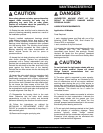
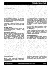
9) Apply increased belt tension by progressively
tightening the take-up capscrews against the
engine/electric motor.
a) Recheck V-belt alignment.
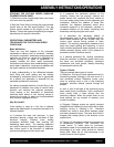
b) Check belt tension with the spring scale or belt
tension tool midway between the engine/electric
motor and arbor shaft pulleys. Belt deflection should
measure approximately .20 inch at 4 to 5-1/2
pounds force. FIGURE 39.
FIGURE 39