


RCC130H-CRACK SAW OPERATION AND PARTS MANUAL REV #1 (11/18/04) PAGE 20
ASSEMBLY INSTRUCTIONS/OPERATIONS
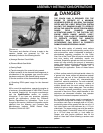
PROPER QUANTITY OF PERSONNEL IN
PROPER PHYSICAL CONDITION.
The integral lifting bail device(s) can be used to
facilitate lifting by a mechanical device incorporating
a chain and suitable attachment device. The location
of the lifting bail(s) may not always locate the exact
position of the center of gravity for the Crack Saw.
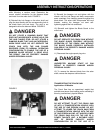
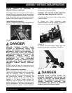
Typical Hoisting Configuration
FIGURE 7 depicts a typical hoisting configuration for
a Crack Saw with a mechanical lifting device.
FIGURE 10
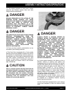
DANGER
EXERCISE EXTREME CAUTION WHEN
UTILIZING A MECHANICAL DEVICE FOR
LIFTING THE CRACK SAW. UTILIZE THE
MECHANICAL DEVICE IN ACCORDANCE TO
BOTH ITS STATED STATIC AND DYNAMIC
LOADING ENVELOPES. DO NOT UTILIZE THE
MECHANICAL DEVICE UNTIL THIS
INFORMATION IS PROPERLY KNOWN AND
UNDERSTOOD BY ALL APPLICABLE
PERSONNEL. FAILURE TO PROPERLY UTILIZE
THE MECHANICAL DEVICE CAN RESULT IN
PROPERTY DAMAGE AND/OR PERSONAL
INJURY.
8) Once on the job site, the Crack Saw can be
lowered to the work surface by reversing the above
steps.
General Transportation Information.
When transporting the Crack Saw on a motor
vehicle, the fuel tank breather vent (if so equipped)
must be completely closed to eliminate the
accidental seepage of fuel and resulting potential fire
and environmental hazards. To minimize the
possibility of damage to the Crack Saw, always
transport in its normal, upright position. All
equipment must be secured in/on vehicles with
suitable strapping or tie-downs. Personnel should
not be transported in the same compartment as
equipment and fuel supplies. Consult applicable
OSHA, AGA, CGA, etc. regulations for the proper
transportation of flammable gases.
STARTING THE RCC130H SERIES GASOLINE
POWERED CRACK SAW ON THE JOB SITE.
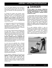
1) Position the Crack Saw on a flat and level surface
of firm foundation.
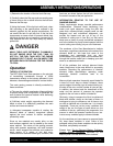
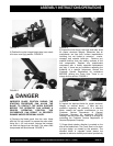
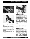
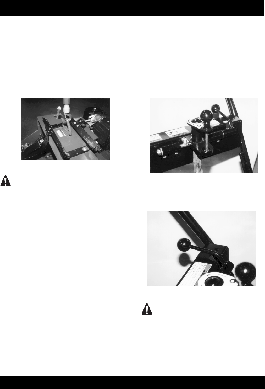
2) Rotate the height adjustment lever
counterclockwise to raise the blade to its maximum
position above the work surface. FIGURE 15.
FIGURE 15
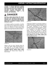
3) Position the quick-change height lever over
center to its rear most (up) position. FIGURE 16.
FIGURE 16
DANGER
IMPROPER BLADE POSITION DURING THE
STARTING PROCEDURE CAN ALLOW THE
BLADE TO CONTACT THE WORK SURFACE
BEFORE THE OPERATOR CAN ASSUME A
PROPER OPERATING POSITION. THIS
OCCURRENCE CAN RESULT IN IMPROPER
DAMAGE AND/OR PERSONAL INJURY.