


RCC130H-CRACK SAW OPERATION AND PARTS MANUAL REV #1 (11/18/04) PAGE 18
ASSEMBLY INSTRUCTIONS/OPERATIONS
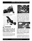
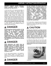
FIGURE 1
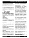
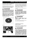
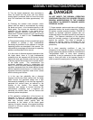
3) Position the quick change height lever over center
to its rear most (up) position. FIGURE 2.
FIGURE 2
DANGER
IMPROPER BLADE POSITION DURING THE
STARTING PROCEDURE CAN ALLOW THE
BLADE TO CONTACT THE WORK SURFACE
BEFORE THE OPERATOR CAN ASSUME A
PROPER OPERATING POSITION. THIS
OCCURRENCE CAN RESULT IN PROPERTY
DAMAGE AND/OR PERSONAL INJURY.
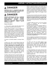
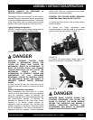
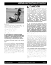
4) Remove the blade guard from the main frame
with the 3/4 inch wrench to expose the arbor shaft.
Using the 1-1/2 inch wrench, remove the hexagon
nut and hub flange from the shaft. The arbor shaft
incorporates left hand threads. FIGURE 3.
FIGURE 3
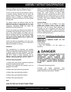
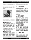
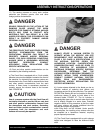
5) Inspect the hub flange, hub body and arbor shaft
for proper structural integrity. Determine that all
components are free from surface imperfections
including, but not limited to corrosion, cracks,
warpage and material build-ups. Remove any
material build-up from the mating surfaces of the
hub components. Replace any questionable
component with a factory approved replacement
part only. If there are any questions regarding the
suitability of a specific component, contact the
Customer Service Department for assistance
BEFORE utilizing the Crack Saw. There is no
charge for this service. FIGURE 4.
FIGURE 4
6) Inspect the diamond blade for proper structural
integrity as outlined above. If there are any
questions regarding the suitability of a diamond
blade, contact the specific manufacturer or the
Customer Service Department of General
Equipment Company for assistance BEFORE
utilizing it with the Crack Saw. There is no charge for
contacting the Customer Service Department of
General Equipment Company.
7) Proper blade rotation direction is marked on the
side of the blade blank. The Crack Saw is of a down
cut type design as viewed by the operator. The
diamond blade is intended rotate toward the
operator to enhance visibility and overall productivity