


STOW CUTTER 3 CE SAW — PARTS & OPERATION MANUAL — REV. #5 (09/22/06) — PAGE 39
Blade Shaft Bearing Replacement
Although the steps for this operation are listed here, it is recom-
mended that this procedure be performed by an authorized ser-
vice center.
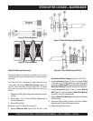
The Cutter 3 CE saw is supported by “tapped base lock collar
(w/set screw)" self-aligning
Blade Shaft Bearings
(Figures 57
and 58). These heavy duty bearings support the 1-1/4 blade
shaft, and have grease (zerk) points conveniently located for
service.
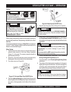
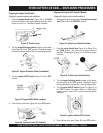
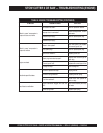
Figure 57. Blade Side Bearing (Right Side)
1. Replace both left & right bearings. Never replace one and not
the other.
2. Follow steps 1 thru 4 of Drive V-Belt(s) Replacement &
Tension Adjustments.
3. Remove Drive V-belts.
Reference Figure 57 & Figure 58 for steps 4-9
4. Remove
Blade Hex Nuts
(Figures 57 & 58, item 1) and
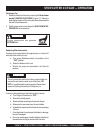
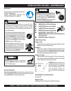
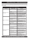
Figure 58. Pulley Side Bearing (Left Side)
STOW CUTTER 3 CE SAW — MAINTENANCE
Outside/Inside Blade Flanges
(Figures 57, item 2 & 3)
5. Loosen
set screws
(Figure 58, item 4) and slide
Pulley
(Figure 58, item 5) off the Blade Shaft. Loosen Bearing set
screw, remove
Bearing Bolt
(Figure 58, item 6) and slide the
Blade Shaft Bearing
(Figure 58, item 8) off the blade shaft.
6. Loosen
set screws
(Figure 57, item 5), remove
Bearing
Bolt
(Figure 57, item 4) and slide the
Blade Shaft Bearing
(Figure 57, item 6) off the blade shaft.
7. Replace
Blade Shaft Bearings
and reassemble the Blade
Shaft Assembly.
8. Re-tension Drive V-belts as shown in the Drive V-Belt(s)
Replacement & Tension Adjustments section.
10. Replace all guards and covers.
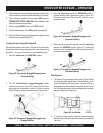
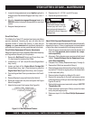
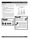
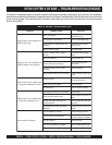
Figure 56. V-Belt Alignment
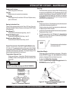
Figure 55. Pulley Alignment