


STOW CUTTER 3 CE SAW — PARTS & OPERATION MANUAL — REV. #5 (09/22/06) — PAGE 3
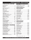
STOW CUTTER 3 CE SAW — TABLE OF CONTENTS
SELF-PROPELLED MODELS ONLSELF-PROPELLED MODELS ONL
SELF-PROPELLED MODELS ONLSELF-PROPELLED MODELS ONL
SELF-PROPELLED MODELS ONL
YY
YY
Y
Battery Assembly .................................................... 78-79
Transmission Engage Lever Assembly .................... 80-81
Hydrostatic Transmission Assembly ........................ 82-83
Hydrostatic Drive Assembly .................................... 84-85
HONDA GX390K1QWT2
GASOLINE ENGINE
Air Cleaner Assembly .............................................. 86-87
Camshaft Assembly ................................................ 88-89
Carburetor Assembly ............................................... 90-91
Control Assembly .................................................... 92-93
Crankcase Cover Assembly .................................... 94-95
Crankshaft Assembly .............................................. 96-97
Cylinder Barrel Assembly ........................................ 98-99
Cylinder Head Assembly ......................................100-101
Fan Cover Assembly ............................................102-103
Flywheel Assembly ..............................................104-105
Fuel Tank Assembly .............................................106-107
Ignition Coil Assembly ..........................................108-109
Muffler Assembly .................................................110-111
Piston Assembly ..................................................112-113
Recoil Starter Assembly ...................................... 114-115
Labels ...................................................................116-117
HONDA GX620TXF2
GASOLINE ENGINE
Air Cleaner Assembly ...........................................118-119
Camshaft Assembly ............................................. 120-121
Control Assembly .................................................122-123
Control Box...........................................................124-125
Crankcase Cover Assembly .................................126-127
Crankshaft Assembly ...........................................128-129
Cylinder Barrel Assembly ..................................... 130-131
Cylinder Head Assembly ......................................132-133
Fan Cover Assembly ............................................134-135
Flywheel Assembly ..............................................136-137
Ignition Coil Assembly ..........................................138-139
Muffler Assembly .................................................140-141
Piston Assembly ..................................................142-143
Fuel Tank Assembly .............................................144-145
Fuel Pump ............................................................146-147
Carburetor Assembly ............................................148-149
Starter Motor Assembly .......................................150-151
Gasket Kit Assembly ...........................................152-153
Labels ...................................................................154-155
Terms and Conditions of Sale — Parts ....................... 156
STOW CUTTER 3 SLAB SAW
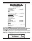
Here's How To Get Help .................................................. 2
Table Of Contents ........................................................... 3
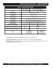
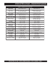
Specifications .............................................................. 4-5
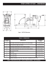
Dimensions ..................................................................... 6
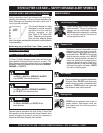
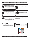
Safety Message Alert Symbols .................................. 7-8
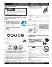
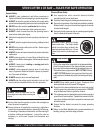
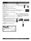
Rules for Safe Operation ........................................... 9-11
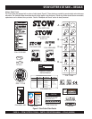
Decals .......................................................................... 12
General Information ...................................................... 13
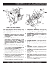
Major Components ....................................................... 14
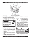
13 HP Engine Components .......................................... 15
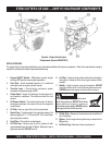
20 HP Engine Components .......................................... 16
Inspection ................................................................ 17-19
Inspection Blade ........................................................... 20
Inspection Blade Placement .................................... 21-22
Inspection-Guards, Covers, and V-Belts ....................... 23
Inspection-V-Belts and Water Tank ............................... 24
Inspection - Adjustments .............................................. 25
Manual Start-up Procedure ...................................... 26-28
Electric Start-up Procedure ..................................... 29-30
Operation ................................................................. 31-34
Shutdown Procedures .................................................. 35
Maintenance ............................................................ 36-41
13HP Engine Wiring Diagram........................................ 42
20HP Engine Wiring Diagram........................................ 43
Troubleshooting (Engine) ......................................... 44-45
Troubleshooting (Blade) ................................................ 46
Explanation Of Codes In Remarks Column .................. 47
Suggested Spare Parts ................................................ 49
COMPONENT DRAWINGS
Nameplate and Decals ............................................ 50-51
Under Carriage Assembly ........................................ 52-53
Blade Shaft Assembly ............................................. 54-55
Lifting Bale Assembly ............................................. 56-57
Console (Push) Assembly ....................................... 58-59
Console (Self-propelled) Assembly.......................... 60-61
13 HP Engine Mount Assembly .............................. 62-63
20 HP Engine Mount Assembly .............................. 64-65
13 HP Engine Assembly ......................................... 66-67
20 HP Engine Assembly ......................................... 68-69
Pointers And Covers ................................................ 70-71
Water System Assembly ......................................... 72-73
Blade Guard Assembly ............................................ 74-75
Manual Raise and Lower Assy. (20 inch) ................. 76-77