


16
4.4 BELT SERVICE
On self-propelled mowers, the engine belt transmits
power from the engine to the transmission that powers
the rear wheels. Should the belt become worn, it could
cause slippage, which would impair mower perform-
ance. The condition of the engine belt should be
checked after every 25 hours of mower operation.
4.4.1. Engine Drive Belt Replacement
1. Empty fuel tank.
2. Remove blade. Refer to Section “Blade
Sharpening”.
3. Remove rear cover of mower. Refer to Section
“Rear Cover Removal & Installation”.
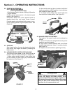
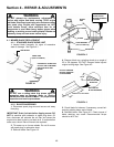
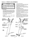
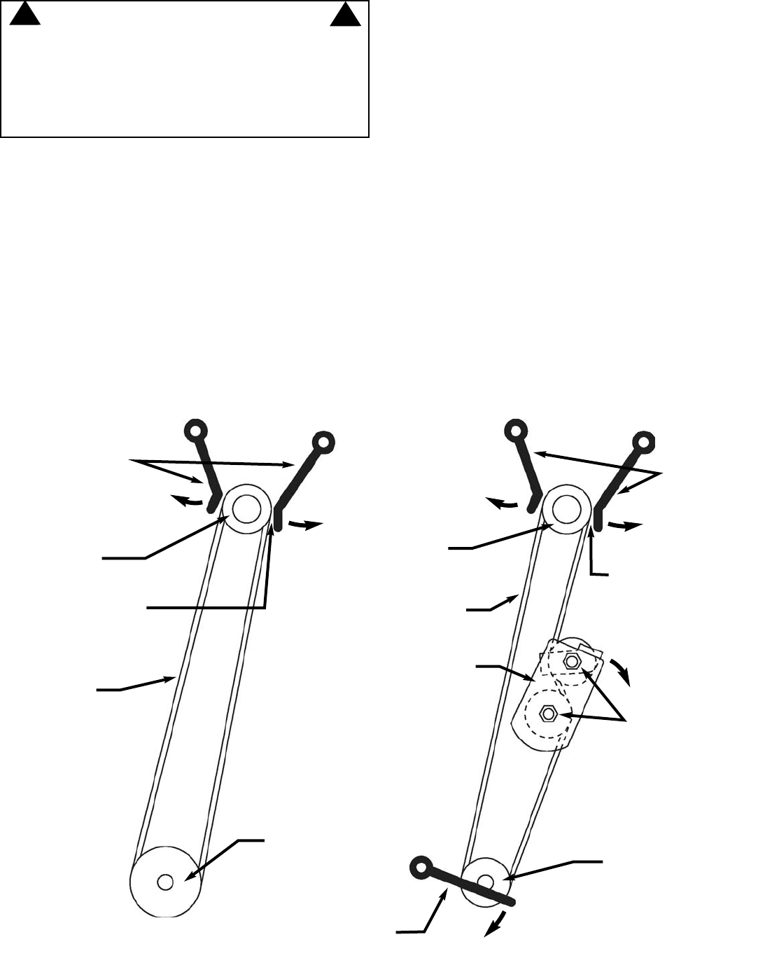
4. SINGLE SPEED MODELS
a. Loosen (do not remove) engine mounting bolts
securing belt guides, and swing belt guides out away
from engine pulley. See Figure 4.8.
b. Replace belt, noting belt routing in Figure 4.8.
c. Replace belt guides, allowing approx 1/16” spacing
between guides and belt. Torque engine mounting
bolts to 40 ft-lbs.
d. Replace blade and rear cover.
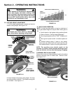
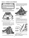
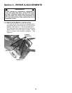
5. VARIABLE SPEED MODELS
a. Loosen (do not remove) engine mounting bolts
securing belt guides, and swing belt guides out away
from engine pulley. Also loosen nut securing transmis-
sion belt guide, and swing guide back away from
transmission pulley. See Figure 4.9.
b. Loosen (do not remove) nuts securing ground
speed idler pulleys to idler plate to ease removal of
belt. See Figure 4.9.
c. Replace belt, noting belt routing in Figure 4.9.
d. Replace belt guides, allowing approx 1/16” spacing
between guides and belt. Torque engine mounting
bolts to 40 ft-lbs. Retighten idler pulley bolts, making
sure idler belt guide is aligned as shown in Figure 4.9.
e. Replace blade and rear cover.
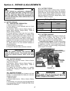
Section 4 - REPAIR & ADJUSTMENTS
WARNING
DO NOT attempt any maintenance, adjustments or
service with engine and blade running. STOP engine
and blade. Disconnect spark plug wire and secure
away from spark plug. Engine and components are
HOT. Avoid serious burns, allow sufficient time for all
components to cool.
!
!
FIGURE 4.9
LOOSEN ENGINE
MOUNTING
BOLTS; SWING
BELT GUIDES
AWAY FROM
ENGINE PULLEY
REPLACE
DRIVE BELT
GROUND
SPEED IDLER
ENGINE
PULLEY
LOOSEN (DO
NOT REMOVE)
THESE NUTS
LOOSEN ENGINE
MOUNTING BOLTS;
SWING BELT GUIDES
AWAY FROM ENGINE
PULLEY
WHEN REPLACING BELT
GUIDES, ALLOW 1/16”
SPACING BETWEEN BELT
GUIDE AND BELT
WHEN REPLACING BELT
GUIDES, ALLOW 1/16”
SPACING BETWEEN BELT
GUIDE AND BELT
ENGINE
PULLEY
TRANSMISSION
PULLEY
REPLACE
DRIVE BELT
SINGLE
SPEED
MODELS
TRANSMISSION
PULLEY
LOOSEN NUT; SWING
BELT GUIDE AWAY FROM
TRANSMISSION PULLEY
FIGURE 4.8