7
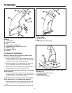
Handle and Latch Installation
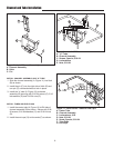
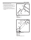
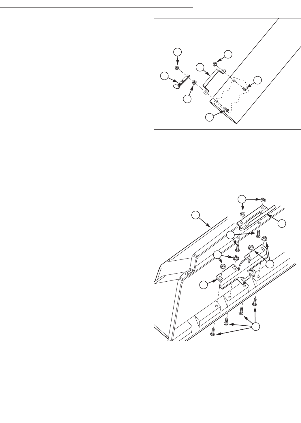
Figure 9. Handle to Tube Installation
A. Handle
B. Locknuts, KEPS, 1/4-20
C. Screw, Slotted, 1/4-20 x 1/2
D. Screw, Slotted, 1/4-20 x 1
E. Strap, Rubber
F. Locknut, Center Lock, 1/4-20
HANDLE INSTALLATION
1. Install the handle (A, Figure 9) using 1/4-20 x 1/2
screw (C) and 1/4-20 locknut (B) for rear hole. Use
1/4-20 x 1 screw (D) and 1/4-20 locknut (B) as
shown. Tighten hardware.
2. Install the strap (E) to screw (D) securing with 1/4-20
locknut (F).
B
D
B
F
A
E
C
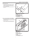
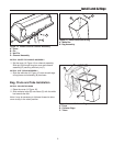
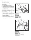
Figure 10. Install Latch & Hinge to Cover Assembly
A. Cover Assembly
B. Latch
C. Locknuts, ESNA, #10-24
D. Screws, #10-24 x 5/8
E. Hinge
F. Locknuts, 1/4-20
G. Screw, Slotted, 1/4-20 x 1/2
A
D
C
B
F
E
F
G
INSTALL LATCH AND HINGE TO COVER ASSEMBLY
1. Install the latch (B, Figure 10) to the cover assembly
(A) securing with #10-24 x 5/8 screws (D) and #10-24
locknuts (C) as shown.
2. Install the hinge (E) to cover assembly securing with
1/4-20 x 1/2 screws (G) and 1/4-20 locknuts (F).


