


22
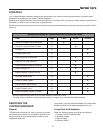
Troubleshooting & Repair
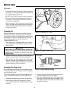
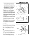
4. Using leather work gloves to protect your hands from
sharp edges, carefully rotate the rotor counterclock-
wise until the first worn hammer is at the top position.
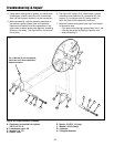
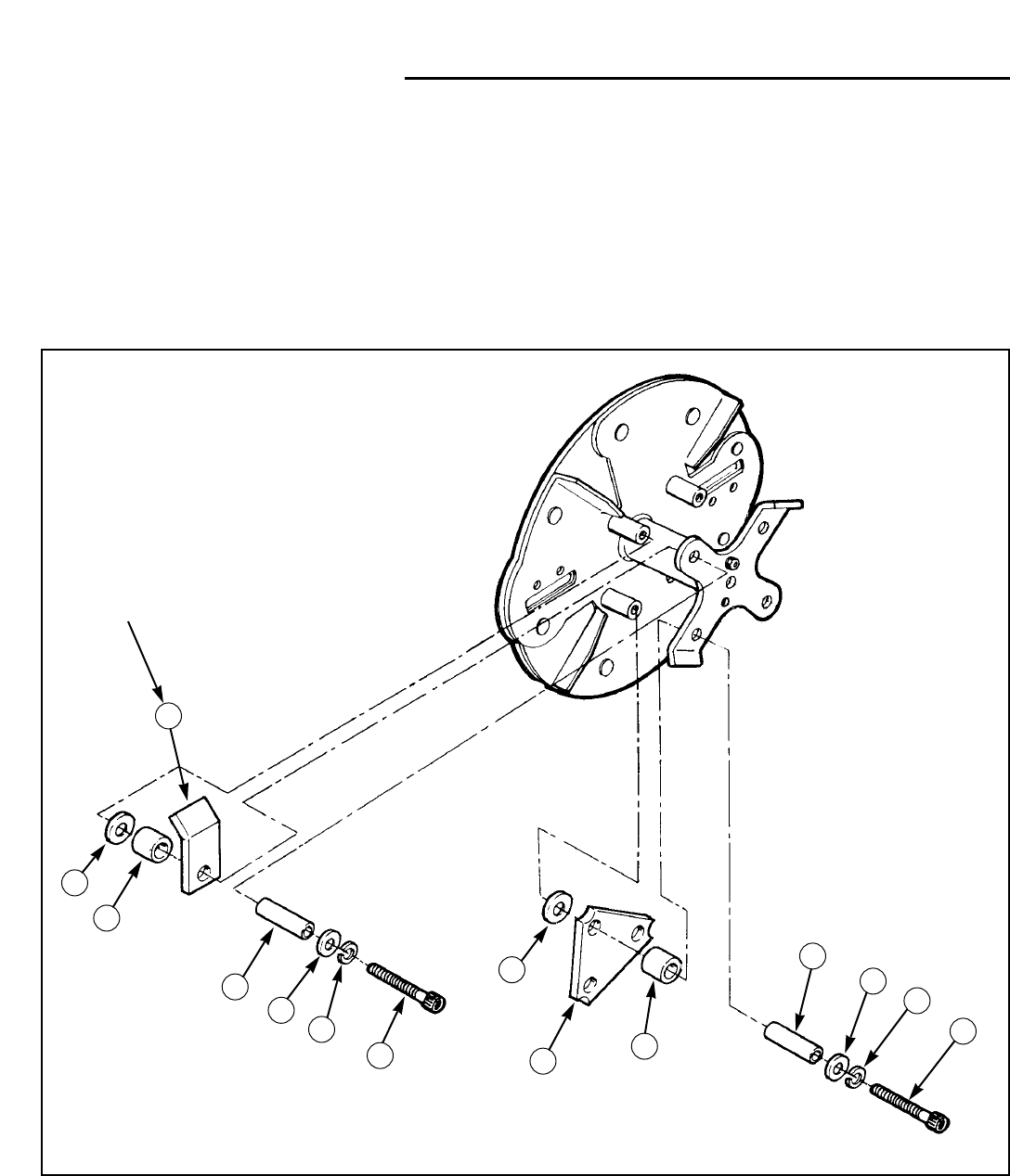
5. Before proceeding, note the assembly sequence of
the hammer, spacer, spacer tube, and hardware.
Hammers and spacers must be reassembled in the
same order to ensure proper rotor balance, shredding
efficiency, and safety. See Figure 20 for correct posi-
tion of parts.
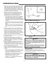
6. See Figure 20. Using a 5/16” Allen wrench, remove
the socket head capscrew (A), lockwasher (B), flat
washer (C), and spacer tube (D), being careful to
catch the parts as the capscrew is removed.
7. Wipe the hammer and spacer tube clean, and inspect
for excessive wear.
• If the spacer tube has light grooves worn into it, the
tube may be reused by flipping its position over
when reinstalling it.
**2479
A
B
C
D
E
H
F
A
B
C
D
E
G
F
The J Hammer (G) on the opposite
side of the rotor faces outward for
balanced rotation.
Figure 20. Proper Hammer Assembly
A. Capscrew, hex socket hd. w/patch,
3/8-16 x 2, Gr. 8
B. Lockwasher, split, 3/8
C. Washer, flat, 7/8
D. Spacer, tube
E. Spacer, 3/4 O.D., 3/4 long
F. Washer, 3/8 (814 only)
G. J hammer
H. Triangular hammer