


27
Section 4 - ADJUSTMENTS & REPAIR
WARNING
The electrolyte (acid) produces a highly explosive gas.
Keep all sparks, flame and fire away from area when
charging battery or when handling electrolyte or
battery. Electrolyte (acid) is a highly corrosive liquid.
Wear eye protection. Wash affected areas immediately
after having eye or skin contact with electrolyte (acid).
Battery acid is corrosive. Rinse empty acid containers
with water and mutilate before discarding. If acid is
spilled on battery, bench, or clothing, etc., Flush with
clear water and neutralize with baking soda. DO NOT
attempt to charge battery while installed on the RIDER.
DO NOT use “BOOST” chargers on the battery.
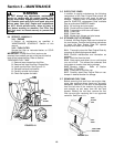
4.6.3. BATTERY SERVICE
1. Remove battery. Refer to Section “BATTERY
REMOVAL”.
2. Place battery in a well ventilated area on a level
surface.
3. Using distilled water, refill cells as required to
cover cell plates of which can also be visualized
through the plastic battery case.
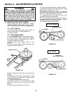
4. With cell caps removed, connect battery charger
to battery terminals. Red to positive (+) terminal
and black to negative (-) terminal.
5. Slow charge battery at 1 amp for 10 hours.
6. If battery will not accept charge or is partially
charged after 10 hours of charging at 1 amp,
replace with new battery.
4.6.4. BATTERY STORAGE
If mower is to be stored out of season on its rear
bumper, it is recommended the battery be
removed, charged and stored.
1. Remove battery. Refer to Section “BATTERY
REMOVAL”.
2. Perform battery service.
3. Bring battery to full charge, if required.
4. Store battery in an area away from the RIDER on
a wood surface. DO NOT STORE BATTERY ON A
CONCRETE SURFACE.
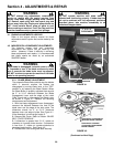
4.6.5. NEW BATTERY PREPARATION
1. Remove battery from carton.
2. Place battery in a well ventilated area on a level
non-concrete surface.
3. Remove battery cell caps. Fill cells as required
with electrolyte (purchased separately) to proper
level. Filling battery with electrolyte will bring the
battery to 80% charged state.
4. With cell caps removed, connect battery charger
to battery terminals; RED to positive (+) and BLACK
to negative (-) terminal.
WARNING
DO NOT attempt to charge battery while installed on
the Riding Mower. DO NOT use “BOOST” chargers on
the battery. DO NOT OVERFILL!
5. Slow charge the battery at 1 amp for 2 hours to
bring the battery to full charge.
6. After charging, check level of electrolyte and
add as needed to bring level to 3/16” above cell
plates.
7. Reinstall cell caps.
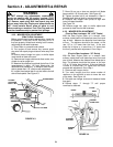
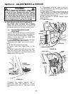
8. Remove the hair pin and swivel from the deck
support to allow clearance for battery installation.
9. Slide battery partially into battery housing.
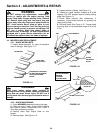
10. Connect positive (+) cable (red) first, from wiring
harness to the positive terminal (+) on battery using
bolt and nut provided in hardware bag. Connect
negative (-) cable (black) last, to negative terminal (-)
on battery using bolt and nut. Apply a small amount
of grease over terminals to prevent corrosion.
11. Insert battery completely into battery housing.
12. Reinstall battery cover. See Figure 4.17.
13. Reinstall swivel and hair pin for deck support.
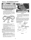
4.6.6. BATTERY TESTING
There are two types of battery tests: Unloaded and
Loaded. The unloaded test is the procedure that
will be discussed. It’s the simplest and most
commonly used. An unloaded test is made on a
battery without discharging current. To perform
unloaded testing, check charge condition using
either a hydrometer or voltmeter.
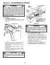
1. Using a voltmeter, voltage readings appear
instantly to show the state of charge. Remember to
hook the positive lead to the battery’s positive
terminal, and the negative lead to the negative
terminal.
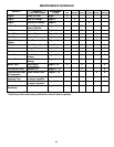
2. A hydrometer measures the specific gravity of
each cell. The specific gravity tells the degree of
charge; generally, a specific gravity of about 1.265
to 1.280 indicates full charge. A reading of 1.230 to
1.260 indicates the battery should be charged. The
chart on the next page shows the charge level as
measured by syringe float hydrometer, digital
voltmeter and five ball hydrometer.
WARNING
Shield the positive terminal with terminal cover
located on battery harness. This prevents metal from
touching the positive terminal, which could cause
sparks.
(Battery Testing Chart on Next Page)