


21
Section 4 - ADJUSTMENTS & REPAIR
WARNING
DO NOT attempt any adjustments, maintenance,
service or repairs with the engine running. STOP
engine. STOP blade. Engage parking brake. Remove
key. Remove spark plug wire from spark plug and
secure away from plug. Engine and components are
HOT. Avoid serious burns, allow all parts to cool
before working on machine. Fuel Filler Cap and vent
must be closed securely to prevent fuel spillage.
4.2.2. MOWER DECK ADJUSTMENT
(Side-To-Side Levelness)
Before making deck leveling adjustments, check the
tire pressure. Front tires 12 PSI, rear tires 12 PSI. If
tires are properly inflated and mowing is still uneven,
adjust side-to-side deck levelness.
1. Place Rider on a smooth level surface.
2. Turn engine off and remove key, remove spark
plug wire from spark plug and secure wire away from
plug.
3. Place a piece of angle iron, pipe, or similar object
under center of deck at the rear.
4. Remove rear hanger chains and allow center, rear
of deck to rest on angle iron.
5. Measure the distance from blade tips to floor. If the
measurement is within 1/8” from side-to-side, the
deck attitude is satisfactory. If difference from side-to-
side is greater than 1/8”, continue with adjustment.
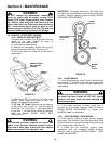
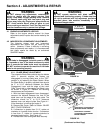
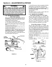
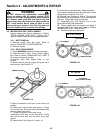
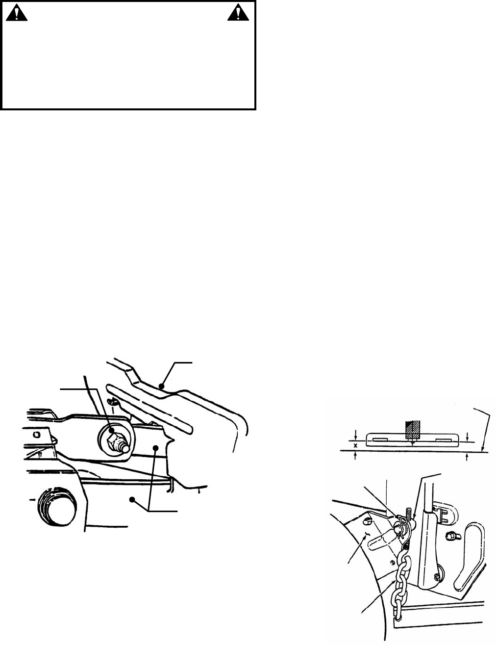
6. Loosen the shoulder bolt & nut that retains the left
side of blade pedal. See Figure 4.3.
FIGURE 4.3
7. Move lift arm up or down as required until blade
tips are within 1/8” of each other. See Figure 4.3.
8. Tighten shoulder bolt & nut loosened in Step 6.
Recheck both sides of deck for correct levelness.
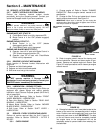
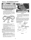
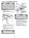
9. Readjust rear hanger chain pivots to align with
holes in support brackets.
See Figure 4.4.
10. Remove angle iron, pipe, or similar object and
proceed to check front to rear levelness.
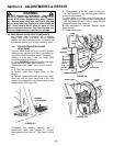
4.2.3. MOWER DECK ADJUSTMENT
(Front to Rear Levelness - 28”, & 33” Decks)
With the Rear Engine Rider on a smooth, level
surface, rotate blade until blade tips are at front and
rear of deck. Measure the distance from blade tips
to floor. The distance should be the same, or the
rear 1/8” to 1/4” lower than the front. If the rear
blade tip is higher or is more than 1/4” lower than
the front, proceed with adjustment. Go to Step 1.
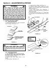
(Front to Rear Levelness - 30” Decks)
With the Rear Engine Rider on a smooth, level
surface, rotate blade until blade tips are at front and
rear of deck. Measure the distance from blade tips to
floor. The distance should be the same, or the rear
1/8” to 1/4” higher than the front. If the rear blade tip
is lower or is more than 1/4” higher than the front,
proceed with adjustment. Go to Step 1.
1. Remove rear hanger chains.
2. Turn each hanger pivot the same number of
rotations on the eye-bolt to raise or lower the rear
of the deck. See Figure 4.4.
3. Reinstall rear hanger chains and measure blade
tips again.
4. Repeat steps “1” through "3” until proper
levelness is obtained.
FIGURE 4.4
BLADE PEDAL
LOOSEN
SHOULDER
BOLT & NUT
LIFT ARM
FRONT
FLOOR
HANGER
CHAIN PIVOT
REAR
X-1/8”
HAIRPIN
SUPPORT
BRACKET
HANGER
CHAIN