


25
Section 4 - ADJUSTMENTS & REPAIR
WARNING
DO NOT attempt any adjustments, maintenance,
service or repairs with the engine running. STOP
engine. STOP blade. Engage parking brake. Remove
key. Remove spark plug wire from spark plug and
secure away from plug. Engine and components are
HOT. Avoid serious burns, allow all parts to cool
before working on machine. Fuel Filler Cap and vent
must be closed securely to prevent fuel spillage.
4.5 MOWER DRIVE BELT REPLACEMENT
Inspect mower drive belt as described in Section
“CHECK MOWER DRIVE BELT”. Replace belt if
signs of excessive wear and/or damage are present.
4.5.1. BELT REMOVAL
1. Remove mower drive belt cover. Refer to
Section “DRIVE BELT COVER REMOVAL”.
2. Remove old belt.
4.5.2. BELT REPLACEMENT
1. Follow WARNING statement found on this page.
2. Check fuel level in tank. If over 3/4 full, remove
tank. Refer to Section “REMOVING FUEL TANK”. If
3/4 or less, proceed to next step.
3. Carefully stand Rear Engine Rider on rear
bumper.
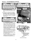
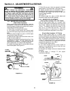
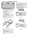
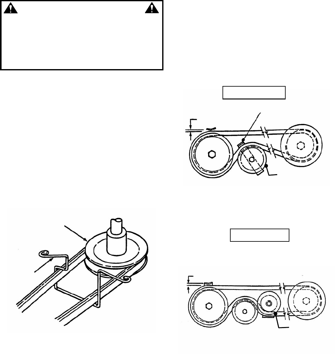
4. Route new belt through engine belt guide up to
engine pulley. See Figure 4.14.
FIGURE 4.14
5. Move transmission shift lever to the neutral (N)
position.
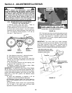
6. Rotate clutch yoke (clutch yoke shown in Figure
4.9) out with your hand and work belt between drive
disc and rubber driven disc.
7. To clear the primary chain case, move
transmission shift lever to the #5 position. Route
belt around drive disc and into drive pulley belt
groove.
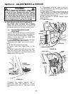
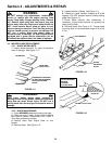
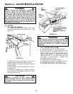
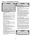
8. Remove idler. See Figure 4.15 and 4.16.
9. Route belt onto spindle pulley. Make sure belt is
inside spindle belt guide and idler belt guide. Route
belt as shown in Figure 4.15 or 4.16.
10. Reinstall idler removed in Step 8. The idler belt
guide tab should be positioned in the hole located on
idler arm. Tighten idler pulley bolt securely.
11. Adjust belt guide. See Figure 4.15 or 4.16 for
proper belt-to-belt guide clearances.
12. Check mower drive belt tension and adjust if
necessary (28” & 30” decks only). Refer to Section
“MOWER DRIVE BELT ADJUSTMENT”.
13. Reinstall mower drive belt cover.
FIGURE 4.15
FIGURE 4.16
ENGINE PULLEY
ENGINE
BELT
GUIDE
1/16” NOMINAL
IDLER BELT GUIDE
28” & 30” DECKS
33” DECKS
1/16” NOMINAL
33” MODELS
(DUAL IDLER SYSTEM)
REMOVE IDLER
REMO
V
E IDLER