


26
Section 4 - ADJUSTMENTS & REPAIR
WARNING
DO NOT attempt any adjustments, maintenance,
service or repairs with the engine running. Stop
engine. Stop blade. Engage parking brake. Remove
key. Remove spark plug wire from spark plug and
secure away from plug. Engine and components are
HOT. Avoid serious burns, allow all parts to cool
before working on machine. Fuel Filler Cap and Vent
must be closed securely to prevent fuel spillage. DO
NOT attempt to service or charge the battery while it
is installed on the machine.
4.6 BATTERY
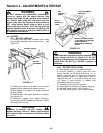
4.6.1. BATTERY REMOVAL
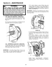
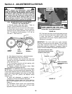
1. Carefully pull each side of battery cover away
from ratchet fasteners and remove cover. See
Figure 4.17.
FIGURE 4.17
2. Remove the hair pin and swivel from the deck
support to allow clearance for battery removal.
3. Slide battery from battery box to gain access to
terminal cables.
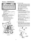
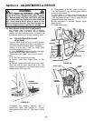
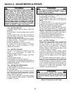
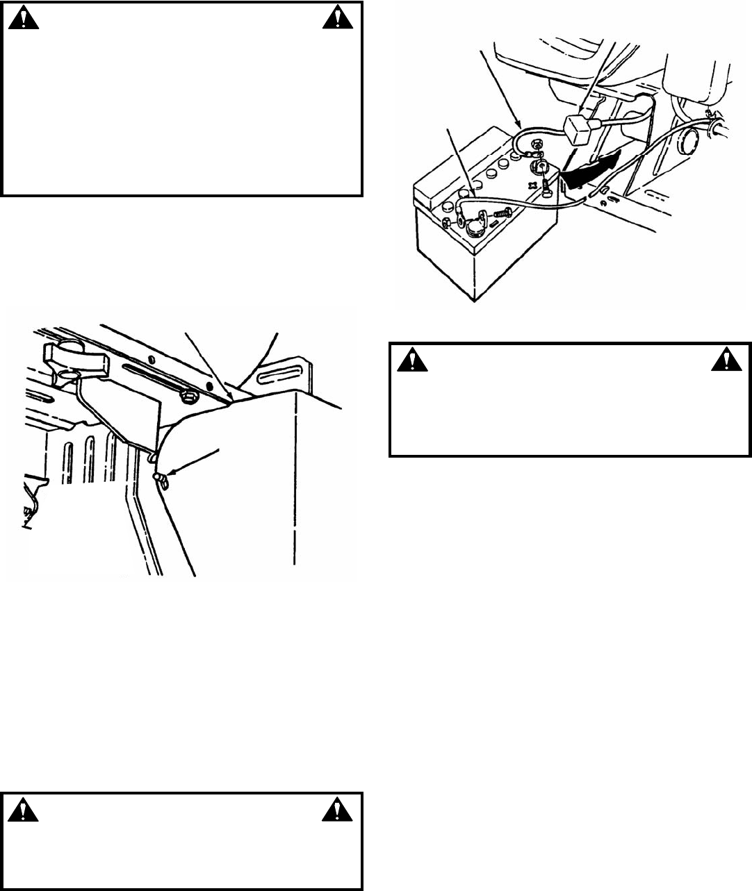
4. Observe and note cable positions on battery.
See Figure 4.18.
5. Disconnect cables from battery terminals,
disconnecting BLACK (Negative) cable first. Retain
mounting bolts and nuts.
CAUTION
If battery is removed, DO NOT operate engine
without insulating Positive + battery cable terminal
with electrical tape, or sparking from battery cables
can result.
FIGURE 4.18
WARNING
Cables must be connected to battery terminals in the
proper position as show in Figure 4.18. DO NOT
attempt to charge battery while installed on the Rear
Engine Rider. DO NOT use “BOOST” chargers on
the battery.
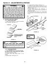
4.6.2. BATTERY INSTALLATION
1. Slide battery partially into battery housing.
2. Connect positive (+) cable (red) first, from
wiring harness to the positive terminal (+) on
battery using bolt and nut provided in hardware
bag. Connect negative (-) cable (black) last, to
negative terminal (-) on battery using bolt and
nut. Apply a small amount of grease over
terminals to prevent corrosion.
3. Reinstall positive terminal insulator.
4. Insert battery completely into battery housing.
5. Reinstall battery cover. See Figure 4.17.
6. Reinstall swivel and hair pin for deck support.
BATTERY COVER
RATCHET
FASTENERS
BLACK
NEGATIVE (-)
CABLE
RED
POSITIVE (+)
CABLE
POSITIVE TERMINAL
INSULATOR
INSTALL BATTERY POSITIVE
(+) END FIRST INTO BATTERY
COMPARTMENT IN
DIRECTION OF ARROW AS
SHOWN