


16
Section 3 – MAINTENANCE
3.2 SERVICE - AFTER FIRST 5 HOURS
3.2.7. SAFETY INTERLOCK SYSTEM CHECKS
Perform the following interlock system checks
periodically during the operating season. Contact your
authorized Snapper dealer if you have questions.
WARNING
DO NOT operate machine if any safety interlock or safety
device is not in place and functioning properly. DO NOT
attempt to defeat, modify or remove any safety device.
ENGINE MUST NOT START IF:
1) Clutch/Brake Pedal is not fully depressed OR,
2) Blade Control is in the “ON” (blades engaged)
position.
ENGINE SHOULD START IF:
1) Blade Control is in the “OFF” (blades
disengaged) position AND,
2) Clutch/Brake Pedal is fully depressed.
ENGINE AND BLADES MUST STOP IF:
1) Operator rises off of seat with Blade Control in
“ON” (blades engaged) position OR,
2) Operator rises off of seat with Clutch/Brake
Pedal not fully depressed.
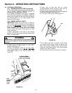
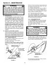
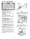
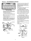
3.2.8. REVERSE LOCKOUT MECHANISM
Check function of Reverse Lockout Mechanism with
engine off.
1. Depress and hold blade pedals.
2. Depress and hold clutch/brake pedal.
3. Shift lever must not go into reverse.
WARNING
DO NOT operate machine if Reverse Lockout
Mechanism is not functioning properly. Contact your
SNAPPER dealer immediately for assistance.
3.2.9. LUBRICATION – GREASE FITTINGS
The following components on the Rear Engine Rider are
equipped with grease fittings and require periodic
lubrication. Apply General Purpose grease (NLGI No.2)
with a grease gun.
1. Front Wheel Bearings. Refer to Section “FRONT
WHEEL BEARINGS – LUBRICATION”.
2. Rear Axle Bearing. Refer to Section “REAR AXLE
BEARING – LUBRICATION”.
3. Mower Blade Spindle. Refer to Section “MOWER
BLADE SPINDLE – LUBRICATION”.
4. Shift Lever. Refer to Section “SHIFT LEVER –
LUBRICATION”.
3.3 SERVICE - EVERY 25 OPERATING HOURS
Perform all service required after the first 5 hours of
operation. Refer to Section “SERVICE – AFTER 5
HOURS”.
3.3.1. CHECK ENGINE
1. Change engine oil. Refer to Section “CHANGE
ENGINE OIL”. Refer to engine owner's manual for oil
specification.
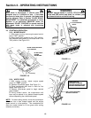
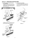
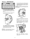
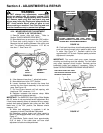
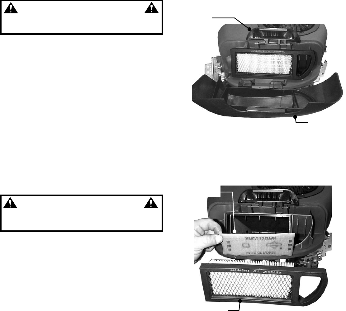
2. Change air filter. Pull up and rotate the air cleaner
latch to remove cleaner cover. See Figure 3.4.
IMPORTANT: When cover is removed, you are viewing the
carburetor side of the air filter, which will appear clean. Remove
filter and pre-cleaner for inspection.
FIGURE 3.4
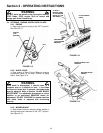
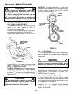
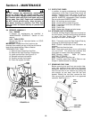
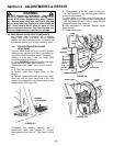
3. Refer to engine owner's manual for cleaning and
service instructions. Remove and clean engine air pre-
cleaner. Remove and replace engine air cleaner. See
Figure 3.5. Install pre-cleaner and air cleaner per engine
owner’s manual.
FIGURE 3.5
4. Reinstall air cleaner cover. Insert tabs located at the
bottom of the cover into corresponding slots in engine
cover. Position cover and engage latch over cover and
rotate and push down to lock. IMPORTANT: The tabs
on the air cleaner cover must be completely inserted
into engine cover or the compartment will not be
completely sealed to prevent debris from entering into
the carburetor.
AIR CLEANER
COVER
AIR CLEANER
LATCH
AIR CLEANER
AIR PRE-
CLEANER
BRIGGS ENGINE SHOWN
BRIGGS ENGINE SHOWN