


22
Section 4 - ADJUSTMENTS & REPAIR
WARNING
DO NOT attempt any adjustments, maintenance,
service or repairs with the engine running. STOP
engine. STOP blade. Engage parking brake. Remove
key. Remove spark plug wire from spark plug and
secure away from plug. Engine and components are
HOT. Avoid serious burns, allow all parts to cool
before working on machine. Fuel Filler Cap and vent
must be closed securely to prevent fuel spillage.
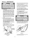
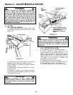
4.2.4. MOWER DRIVE BELT ADJUSTMENT
(FOR 28" & 30” DECKS ONLY)
1. Remove mower drive belt cover. Refer to
Section “CHECK MOWER DRIVE BELT”.
2. Move blade lever up and over to the “ON” position.
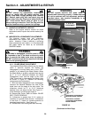
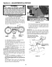
3. Place deck cutting height in the 3rd position.
Measure the belt spacing between idler pulley and
belt. The distance should measure 1-1/4” but no
less than 1”. See Figure 4.5.
FIGURE 4.5
4. If the distance is less than 1”, adjust belt tension.
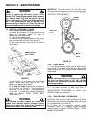
5. Move blade lever to the “OFF” position.
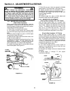
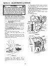
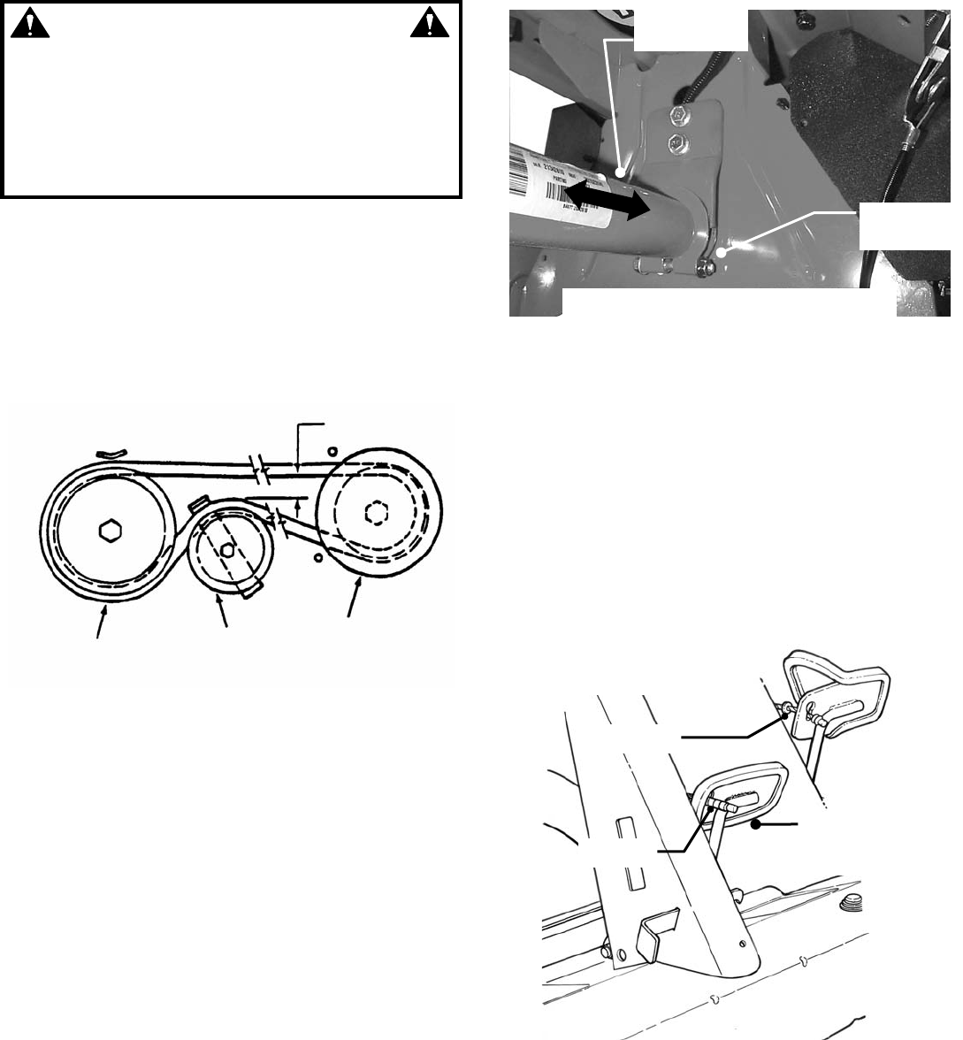
6. Loosen hardware that secures the clamp that
anchors the front frame assembly to the rear main
case. See Figure 4.6.
7. Pull front frame forward until belt spacing, with
blade lever “ON”, measures 1-1/4”.
8. Retighten hardware that secures clamp. Make
sure hardware is tightened securely.
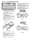
IMPORTANT: The SNAPPER Rear Engine Rider Models
with 33” decks do not require belt tension adjustment. But,
if front frame assembly clamp is loosened for any reason,
recheck belt spacing between idler pulley and belt. With
blade lever in the “ON” position, the distance should
measure 1-3/4”.
9. When belt adjustment is complete it will be
necessary to check Clutch/Brake Cable slack.
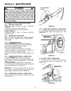
10. Disengage parking brake and allow pedal to
remain in the engaged wheel drive (Up) position. See
Figure 4.7.
11. Clutch/Brake Cable should have approximately
3/16” of slack. If the cable does not have slack
adjustment of cable must be performed.
FIGURE 4.6
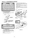
12. Peel back the rubber clutch/brake pedal pad and
push one ferrule through hole in pedal to attain slack
in cable. See Figure 4.7. Recheck cable for the
approximate 3/16” of slack. Replace pedal pad when
adjustment is complete.
IMPORTANT: Too much slack may cause improper
clutching and braking could be affected. Too little slack
may cause improper clutch function. Recheck service
brake/park brake and readjust if necessary. Refer to
Section “SERVICE BRAKE/PARK BRAKE ADJUSTMENT”.
FIGURE 4.7
1-1/4”
SPINDLE
PULLEY
IDLER
PULLEY
ENGINE DRIVE
PULLEY
ASSEMBLY
LOOSEN HARDWARE AND SLIDE FRONT
FRAME ASSEMBLY FORWARD TO OBTAIN THE
DESIRED BELT TENSION MEASUREMENT
LOOSEN
HARDWARE
SLIDE FRONT
END ASSMBLY
PEEL BACK PEDAL PAD. PUSH
ONE FERRULE THROUGH PEDAL.
RECHECK CABLE SLACK
FERRULE
FERRULE
PEDAL IS SHOWN IN
THE ENGAGED OR UP
POSITION