


7
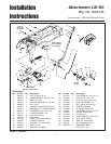
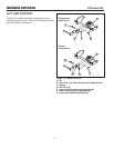
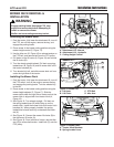
Lift Lever Kit Installation Instructions
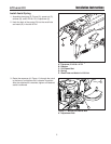
50" Mower, RH Side
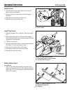
44" Mower, RH Side
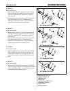
38" Mower, RH Side
40" Mower, RH Side
A
A
B
B
B
B
C
C
C
C
D
D
D
D
E
E
E
E
F
F
C
C
G
G
H
H
H
H
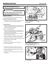
Figure 15. Modify Mower Deck - 44” & 50”
A. Whizlock Nut, 5/16-18
B. Nylock Nut, 5/16-18
C. Washers, 5/16
D. Chain Link
E. Capscrew, 5/16-18 x 1-1/2
F. Capscrew, 5/16-18 x 1
G. New Lift Arm
H. Mower Lift Arm
50” MODELS
Note: Old style only
2. Mount a new lift arm (G, Figure 15) on the inside of
both the left and right mower lift arms (H) using two
5/16-18 x 1 capscrews (F), washers (C), and whi-
zlock nuts (A).
3. Secure chains (D) to the inside of the LH and RH lift
arms (G) using a 5/16-18 x 1-1/2 capscrew (E),
washer (C), and nylock nut (B). The nut should be
snug, but the chain should be able to pivot.
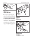
44” MODELS
Note: Some models
2. Mount a new lift arm (G, Figure 15) on the inside of
both the left and right mower lift arms (H) using two
5/16-18 x 1 capscrews (F), washers (C), and whi-
zlock nuts (A).
3. Secure chains (D) to the inside of the LH and RH lift
arms (G) using a 5/16-18 x 1-1/2 capscrew (E),
washer (C), and nylock nut (B). The nut should be
snug, but the chain should be able to pivot.
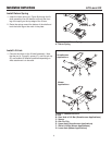
40” MODELS
Note: Some models
2. Secure middle hole of the chains (D) to the inside of
the LH and RH lift arms (H) using a 5/16-18 x 1-1/2
capscrew (E), washer (C), and nylock nut (B). The
nut should be snug, but the chain should be able to
pivot.
38” MODELS
Note: Some models
2. Secure chains (D) to the inside of the LH and RH lift
arms (H) using a 5/16-18 x 1-1/2 capscrew (E), wash-
er (C), and nylock nut (B). The nut should be snug,
but the chain should be able to pivot.