


3
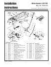
Lift Lever Kit Installation Instructions
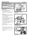
Install Lift Lever & Lift Shaft Assembly
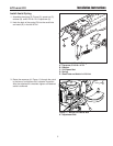
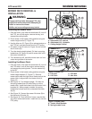
1. Install the lift quadrant (B, Figure 5) using two 5/16-
18 x 1 grade 8 capscrews (C) and flange nuts (A).
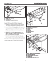
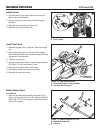
2. Insert the lift lever (F, Figure 6) through the quadrant,
frame, and lift latch (D). NOTE: Route the wire har-
ness and fuel line above the lift lever cross bar. DO
NOT pinch the fuel line and wire harness between
the cross bar and frame.
3. Insert a 5/16-18 x 2-1/4 capscrew through a 5/16
washer (B), lift bar (C), frame, lift latch (D), and lift
lever (F). Secure with a 5/16 locknut.
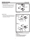
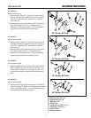
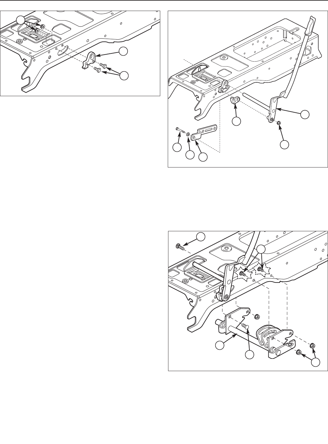
4. Mount the lift shaft assembly (A, Figure 7) to the
frame using three 5/16-18 x 3/4 carriage bolts (B),
5/16-18 x 1-1/2 carriage bolts (D) and flange nuts (C).
Note: If the unit has a single point pick-up for the mower
reinstall the bell crank to the rear right lift shaft hole.
B
C
A
Figure 5. Install Lift Quadrant
A. Flange Nuts, 5/16-18
B. Lift Quadrant
C. Capscrews, Grade 8, 5/16-18 x 1
F
E
D
C
B
A
Figure 6. Install Lift Lever
A. Capscrew, 5/16-18 x 2-1/4
B. Washer, 5/16
C. Lift Bar
D. Lift Latch
E. Locknut 5/16-18
F. Lift Lever
Figure 7. Install Lift Shaft Assembly.
A. Lift Shaft Assembly
B. Carriage Bolts, 5/16-18 x 3/4
C. Flange Nuts
D. Carriage Bolt, 5/16-18 x 1-1/2
B
B
C
A
A