


2
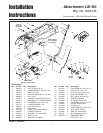
Installation Instructions Lift Lever Kit
INSTALLATION
1. Remove the mower deck (see operator’s manual).
Remove Seat Deck & Tunnel
1. Elevate the rear of the tractor, and support the tractor
on jackstands. Remove the right rear wheel.
2.
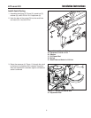
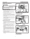
50” MOWER DECKS
Remove and discard the lift lever pivot capscrew (A,
Figure 2) and related hardware. Disconnect and dis-
card the rod (C) and lift lever (B).
38”, 40” & 44” MOWER DECKS
Remove and retain the lift lever pivot capscrew (A,
Figure 2) and related hardware. Disconnect and dis-
card the rod (C) and lift lever (B).
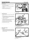
3. Disconnect the seat switch wire harness. Remove
the wire harness from the clip.
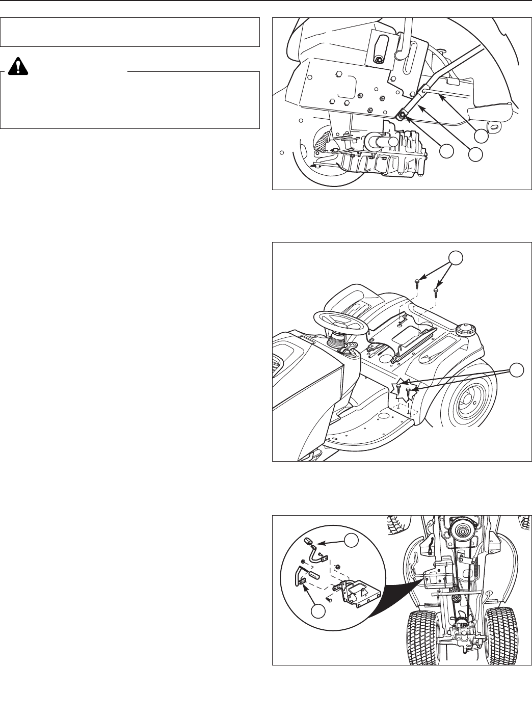
4. Move the seat slide to access the two top seat deck
capscrews (B, Figure 3). Remove the capscrews.
5. Remove the four bolts (A, Figure 3) securing the front
of the seat deck to both footrests.
6. Remove the gas cap.
7. Remove the cruise control knob (if equipped).
8. Remove the seat deck.
This kit adds an attachment lift lever to
Broadmoor/1600/2600 Series lawn tractors.
Before beginning any service work turn off the
PTO, set the parking brake, turn off the ignition,
and disconnect the spark plug wire(s).
WARNING
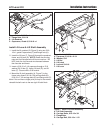
Figure 3. Seat Deck Removal
A. Foot Rest Screws (Two per Side)
B. Top Seat Deck Screws
B
A
Seat Removed
for Clarity
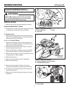
Figure 2. Seat Deck Removal
A. Pivot Capscrew C. Rod
B. Lift Lever
A
C
B
A
A
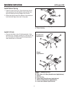
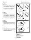
Figure 4. Pedals
A. Foot Pedals
9. Remove the foot pedals (A, Figure 4) and any
remaining screws securing the tunnel to the frame.
10. Pull back on the footrests (tunnel) and remove the
tunnel from the frame.
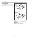
11. Remove the lift lever slot plastic plug from the lower
dashboard.