


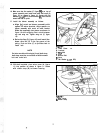


NOTE
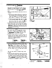
Front belt stop should be installed facing
outside of deck.
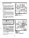
‘6. Install
thefront
belt stop (A, figure4)
onto5/16-
18
x
l-1/2
capscrew
(installed in step 3) as
shown. If removed, reinstall brake spring or
spring anchor (F) before flange nut(G). Tighten
nut (E) snug only
-
belt stop will be adjusted in
step 8.
G Mower Decks
Figure 4.
a
Belt
stop
B.
Capscrew
C. Large Washer
D.
,
n**.“rchn*
E. Nut
F.
Spring or Spring
Anchor
G. Flange Locknut
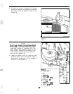
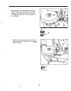
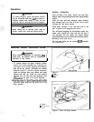
7. Install new double-groove arbor pulley (D,
figure 5) with hub down. Use new 7/16-14
x
2-
1/4
capscrew
and washers removed in step 2.
Torque
to~55
to 70 ft. Ibs. Use wood block to
prevent blade from turning. It may be necessary
to add washer(s) (C, figure 5, two provided)
underneath the new pulley to properly align
brake pad and bottom groove. Referto figure 5.
Add washers to adjust top-to-bottom alignment:
l/16” clearance must be adjusted after belt is
installed and PTO is engaged.
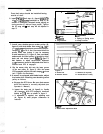
8. Slip the mower drive belt onto the lower groove
of the new pulley (D, figure 2). With the mower
PTO engaged, adjust the belt stops
l/8”
from
belt. Tighten the hardware.
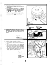
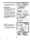
9. If mower is equipped with blade brake, adjust
the brake after installing new double groove
pulley as follows:
a. Engage the PTO lever. Be sure that mower
drive belt tension is correctly adjusted (see
Operator’s Manual).
b. Inspect the brake pad (A, figure5) to V-pulley
(B) clearance. With PTO engaged, clearance
should be
l/l6
inch as shown in figure 5.
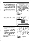
c. If adjustment is required, turn adjusting nuts
(A, figure 6) until proper clearance is
reached.
Figure 5.
A. Brake Pad
B. Bottom Groove
C. Washers (If required)
D. Double-Groove Pulley
Figure
6.
A. Blade Brake Adjustment Nuts