


27
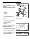
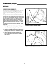
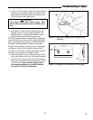
4. Using leather work gloves to protect your hands from
sharp edges, carefully rotate the rotor counterclock-
wise until the first worn hammer is at the top posi-
tion.
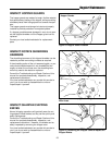
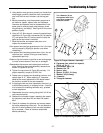
5. Before proceeding, note the assembly sequence of
the hammer, spacer, spacer tube, and hardware.
Hammers and spacers must be reassembled in the
same order to ensure proper rotor balance, shred-
ding efficiency, and safety. See Figure 28 for correct
position of parts.
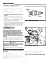
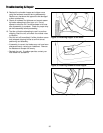
6. Using a 5/16” Allen wrench, remove the socket head
cap screw (A, Figure 28), lockwasher (B), flat washer
(C), and spacer tube (D), being careful to catch the
parts as the cap screw is removed.
7. Wipe the hammer and spacer tube clean, and
inspect for excessive wear.
•If the spacer tube has light grooves worn into it, the tube
may be reused by flipping its position over when
reinstalling it.
•If the spacer tube has deep grooves worn into it, do not
reuse the part - replace it using an exact factory
replacement part only.
•Rotate or flip the hammer to provide a new cutting edge,
or install a new hammer if worn out or damaged.
•Reassemble the hammer and related parts and hard-
ware, observing the correct assembly sequence as
shown in Figures 28 and 29.
8. Tighten the cap screw (A, Figure 28) securely. For
proper assembly, torque to 30-35 ft. lbs.
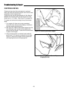
9. Rotate rotor to expose next shredding hammer, and
repeat steps 6 - 8. When replacing “J” hammers,
observe the correct placement of the blade toward
the inside or outside of the rotor assembly.
10. If chipping knives are to be inspected or serviced, go
to the following section on chipping knives. If service
is to be done on shredding hammers only, proceed
to next step below.
11. Reassemble the rotor housing using the 5/16-18 hex
nuts removed earlier.
12. Reattach the shredder hopper, repeating the assem-
bly sequence used when the unit was first assem-
bled.
13. Check all hardware for tightness and correct assem-
bly before attempting to start unit. Do not attempt to
start unit if extra hardware is left over after reassem-
bly is complete. Check all hammer assemblies
before proceeding.
Troubleshooting & Repair
A
B
C
D
E
H
F
A
B
C
D
E
G
F
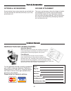
The J Hammer (G) on
the opposite side of the
rotor faces outward for
balanced rotation.
Figure 28. Proper Hammer Assembly
A. Capscrew, hex socket hd. w/patch,
3/8-16 x 2, Gr. 8
B. Lockwasher, split, 3/8
C. Washer, flat, 7/8
D. Spacer, tube
E. Spacer, 3/4 O.D., 3/4 long
F. Washer, 3/8 (814 only)
G. J hammer
H. Triangular hammer
Figure 29. Reassembling Shredder J Hammer
A