


8
GENERAL
All of the major assembly procedures on your new
Chipper/Shredder were performed at the factory, and
only the items listed in this section need to be taken care
of to make your unit fully operational.
TOOLS REQUIRED
• 1/2" Box Wrench or Socket
• 7/16" Box Wrench or Socket
• 1/4" Hex Wrench
• Phillips Screw Driver
• Hex (Allen) Wrench
Assembling the
Chipper Shredder
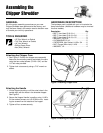
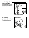
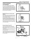
Figure 2. Installing Chipper Cone
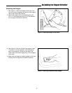
Figure 3. Installing the Hopper Handle
HARDWARE DESCRIPTION
The hardware pack included with your unit contains the
items listed below. (Additional hardware may be involved
for other models.)
Description Qty.
• BOLT, Hex Head 5/16-18 x 1 . . . . . . . . . . . . 1
• BOLT, Hex Head 5/16-18 x 3/4 . . . . . . . . . . 2
• BOLT, Hex Head 5/16-18 x 1/2 . . . . . . . . . . 2
• WASHER, Flat 5/16 . . . . . . . . . . . . . . . . . . . 4
• LOCKWASHER, 5/16. . . . . . . . . . . . . . . . . . 2
• CAPSCREW, Hex Socket 1/4-20 x 3/4 . . . . 6
• NUT, Flange (Whiz-lock) 1/4-20. . . . . . . . . . 6
• WASHER, 1/4. . . . . . . . . . . . . . . . . . . . . . . . 4
Attaching the Chipper Cone
1. See Figure 2. Position the chipper cone assembly
base onto the mounting casting and attach the cone
using the hex socket screws (1/4-20 x 3/4”) and the
1/4” lock nuts provided.
2. Tighten lock nuts securely using a 7/16” wrench or
socket.
Attaching the Handle
1. Lift the hopper handle up until the outer holes in the
handle align with the holes in the shredder hopper.
See Figure 3.
2. Secure the Hopper Handle in position using 1/4-20 x
3/4 hex socket screws, and 1/4-20 Whiz nuts, insert-
ing the screws from the outside of the hopper.
3. Tighten all four screws securely.