


8
CONTROLS AND INSTRUMENTS
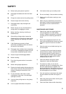
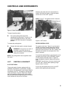
The engine temperature, oil pressure, glow plug and
charge indicator warning lights are located as shown
in Figure 3, When the key start switch is turned “ON”
the oil pressure and charge lights come on. After the
engine has been started, the lights should go out
within a few seconds. If they do not go out:
l Engine oil pressure warning light: Stop the
engine immediately and investigate the
cause. It is important to remember that this
light indicates OLI pressure only. The
operator must regularly check the crankcase
for proper oil level.
l Charge indicator warning light: This is an
indication that the charging system is not
operating normally. Investigate the cause as
soon as possible, otherwise the battery will
become fully discharged.
l Coolant temperature warning light: The
warning light is not on under normal operating
conditions. If the light comes on, stop the
engine and investigate. Regularly check the
radiator for proper coolant level. Function of
the indicator light bulb can be checked by
grounding this light at the thermostat.
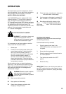
WARNING: When engine is at
operating temperature always relieve
pressure in the cooling system before
removing the radiator cap.
l Glow plug indicator warning light : This light
comes on when turning the key switch to the
“HEAT” position or “START” position. Refer to
page 19 for ‘starting engine information.
NOTE: Make certain that three warning lights except
for the coolant temperature turn on when turning the
key switch to the “ON” position. If one of them does
not turn on, the bulb should be replaced.
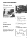
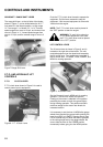
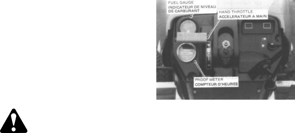
PROOF-METER
The Proof-Meter is located on the left side of the
instrument panel, Figure 4. Turn the key start switch
to the “ON” to operate proof meter.
FUEL GAUGE
The fuel gauge is located on the left side of the
instrument panel, Figure 4.
Figure 4 - Proof Meter, Fuel Gauge and Hand
Throttle
HAND THROTTLE CONTROLS
The hand throttle is shown in Figure 2. Push the
throttle forward to increase engine rpm Pull the
throttle rearward to decrease engine rpm
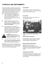
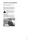
BRAKE CONTROLS BRAKE PEDAL
Brake pedal is shown in Figure 5.
Speed control lever will be returned to the
“RELEASE” position by depressing the brake pedal
suddenly, if the speed control lever is in the “SET”
position
PARKING BRAKE CONTROL
The parking brake latch, shown in Figure 5, is used
for locking the brake pedal in the applied position.
The parking brake should be applied whenever the
tractor is parked.