


ASSEMBLY
Turbo120 01/11 Assembly Section 3-3
© 2011 Alamo Group Inc.
ASSEMBLY
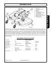
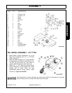
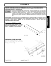
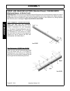
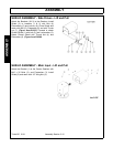
ITEM QTY DESCRIPTION
1. 1 A-Frame - RH
2. 1 A-Frame - LH
3. 2 Brace
4. 1 Brace
5. 2 Hitch Pin
6. 1 Nut
7. 2 Bolt
8. 4 Spacer
9. 2 Nut
10. 2 Bolt
11. 1 Bushing
12. 1 Locknut
13. 1 Bolt
14. 3 Flatwasher
15. 1 Spacer
16. 1 Bolt
17. 2 Bolt
18. 3 Clip
19. 1 Pin
20. 1 Bushing
21. 1 Driveline Holder
22. 1 Axle Pivot Pin
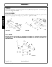
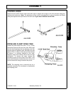
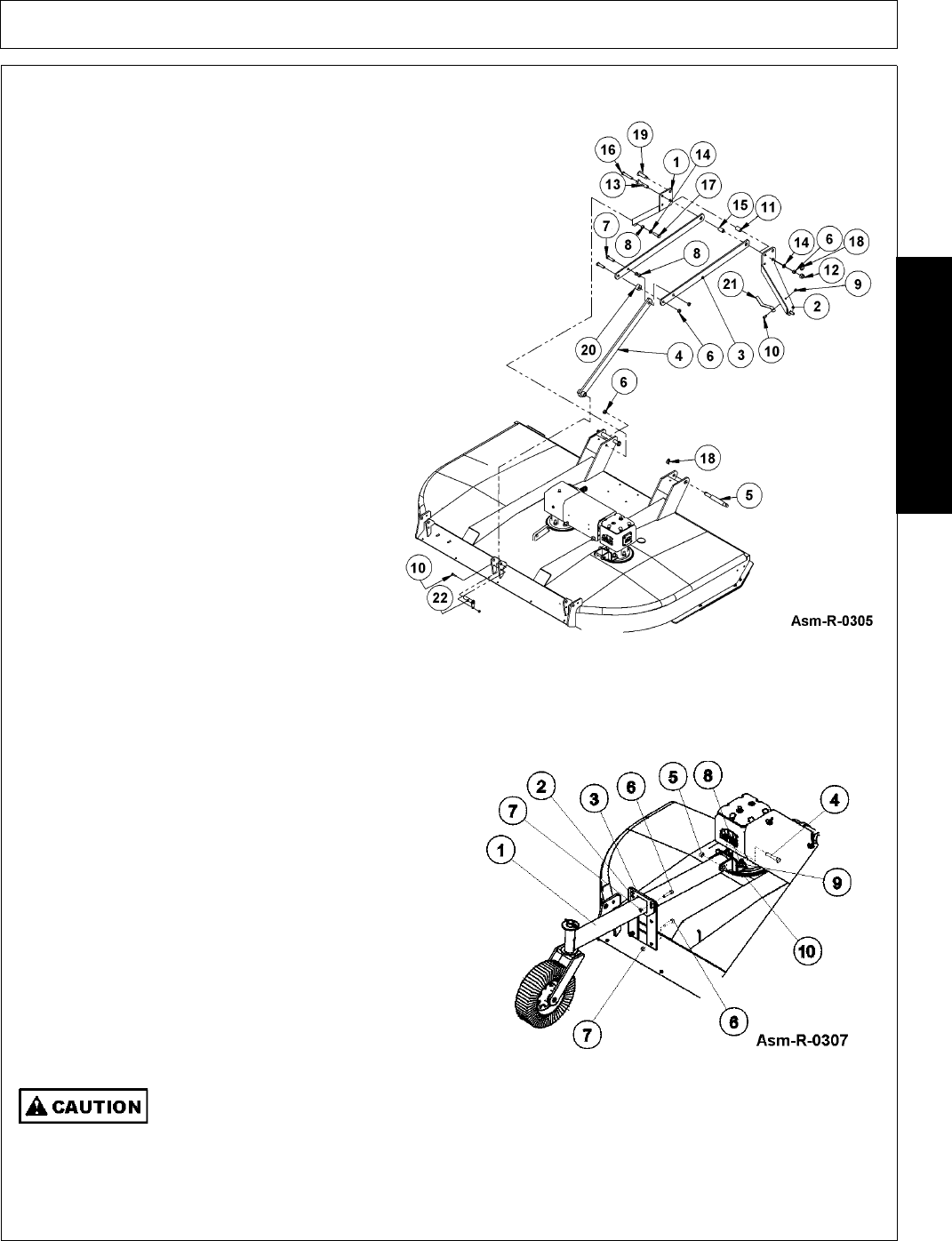
TAIL WHEEL ASSEMBLY - LIFT TYPE
1. Attach Beam Support Weldments (2) to the
Main Frame Assembly with 1/2” x 1-1/2” Bolts
(6) & Locknuts(7).
2. Slide the Beam Weldment (1) through Bracket
(3) and attach to the Mower Lugs with 5/8" x 4-
1/2" Bolt (4) and Locknut (5). Then attach to
gearbox with flatwasher (9) and locknut (8).
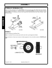
3. Install 1/2” x 1-1/2” Bolts (6) through Beam
Support Weldment (2) and Bracket (3). (Install
through pair of holes which will give
approximate desired cutting height). Install
Locknut (7). Figure Asm-R-0307
‘
The Components of these machines are quite heavy. Block all components up securely
before working under or putting extremities under such parts.