


ASSEMBLY
CY72 01/08 Assembly Section 3-6
© 2008 Alamo Group Inc.
ASSEMBLY
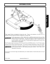
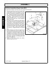
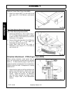
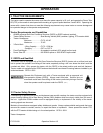
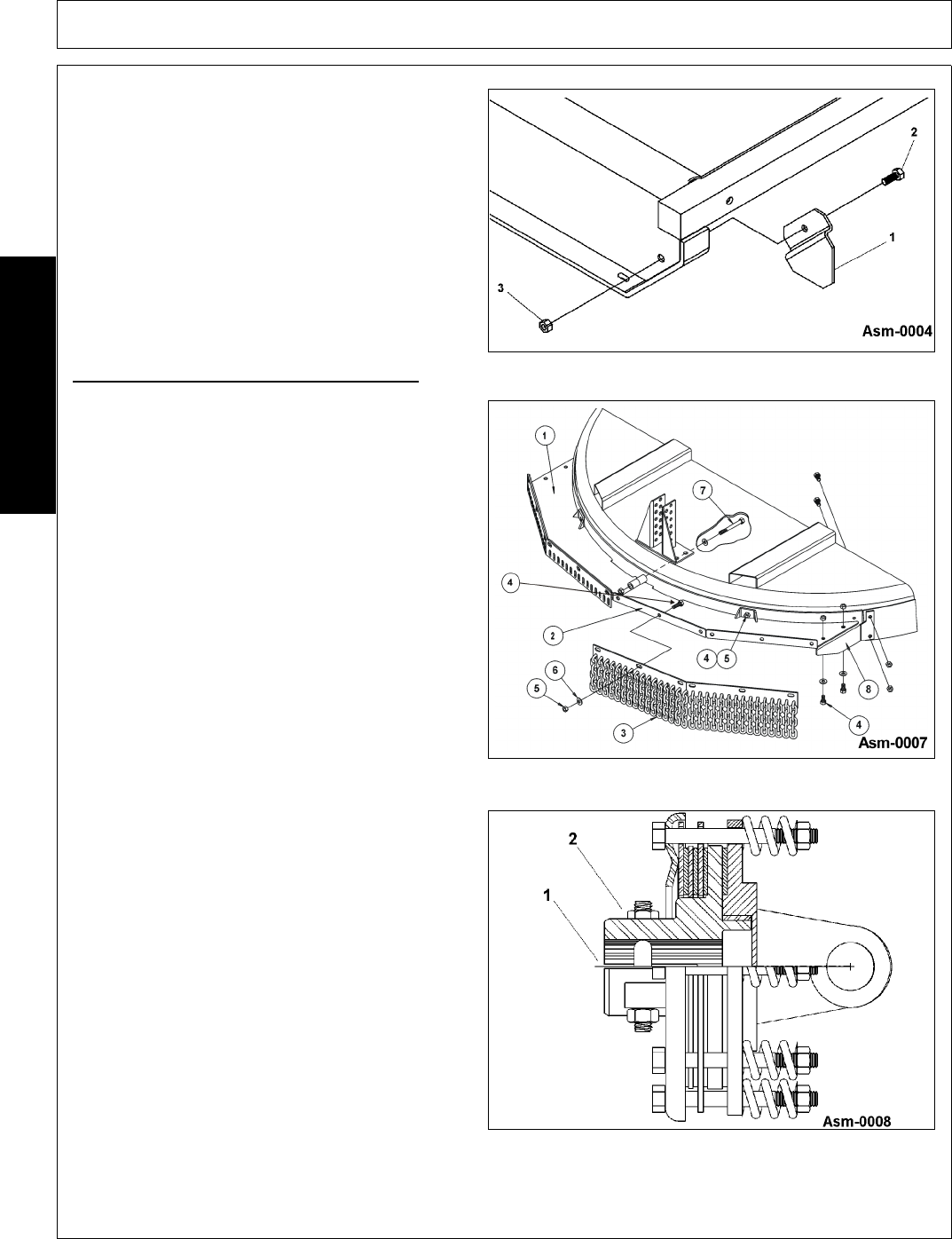
Deflector Corner Plate (Figure Asm-0004)
1. Attach the corner plate (1) to the side of the
deck with a 1/2" x 1-1/4" Bolt (2), and Locknut
(2).
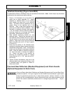
Rear Chain Guards (Optional Equipment)
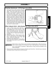
Rear Chain Guard (Figure Asm-0007)
1. Attach both Deflectors (1 & 2) to deck using 1/
2" x 1-1/4" Bolts (4) and Locknuts (5). In center
of deck use Bolt (7) and Locknut (5) to tie both
Deflectors (1 & 2) together.
2. Secure Chainguard Assembly (3) to Deflectors
(1 & 2) using 1/2" x 1-1/4" Bolts (4),
Flatwashers (6), and Locknuts (5).
3. Fasten Rear Plate (8) on both ends of
Deflectors (1 & 2) using 1/2" x 1-1/4" Bolts (4)
and Locknuts (5).
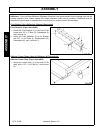
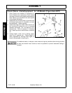
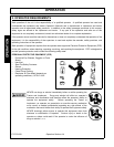
Driveline Attachment - CY60 (Figure Asm-0008)
Before starting assembly, make certain that all
paint, dirt, and grease are removed from gearbox
shaft (1). To ease assembly apply a light coat of
grease to splines and assemble. Do not assemble a
driveline without a shield. Entanglement in rotating
shafts can kill.
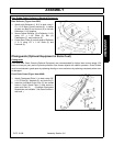
1. Attach the slip clutch end of the driveline to the
gearbox input shaft securely. Make certain that
the slip clutch is fully onto the input shaft
splines. Tighten the locknuts (2) alternately
until they have reached the proper torque.
Refer to Torque Chart in the Maintenance
Section.