


_HROTTLE
i _CABLE
J
HOLE"A"
GOVERNOR
CONTROL
FIGURE 50
FIGURE 51
R.H. SIDE OF TRACTOR
ENGINE
PULLEY
/. _?_ CLUTCH I
IDLER
BRACKET
1-1/16" i | .... t NUT "A"
TAKE. UP
IDLER "
,FIGURE 5:2
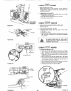
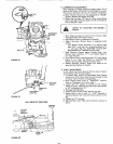
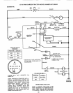
5o CARBURETOR ADJUSTMENT
Never attempt to change maximum engine speed. This is
preset at the factory and should only be changed by aquali-
fied service technician who has the necessary equipment.
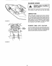
a. Move Throttle Control (on the dashboard) to I_SLOW'*
position. Remove'All: Cleaner (Fig. 36).
b. Check that two holes "A" line up. If not, loosen Clamp
Screw and adjust Throttle Cable until the two holes do
line up (Fig. 50 - Inset),
r
REFER TO "STARTING THE ENGINE",
PAG E 6.
co Start Engine and allow to warm for five minutes. Make
final adjustments with engine running.
d_ High Speed is fixed, no adjustment is possible,,
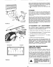
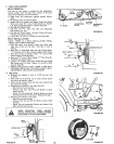
e, Adjust Carburetor Mixture Screw to suggested initial
setting,
-- Turn Mixture Screw clockwise (/_) closing finger
tight ONLY, and then turn counterclockwise (f'_)
1 - t/2 turns (Fig. 51).. CAUTION: VALVE MAY
BE DAMAGED IF TURNED IN TOO FAR.
f. Hold Governor Control against Throttle Stop. Turn
Mixture Screw clockwise (('_) until engine begins to
run rough (Fig. 51).
g. Turn Mixture Screw counterclockwise (_) until engine
begins to run rough,. Set Mixture at smoothest idle
between the two points attained in steps f and go
h. Release Governor Control. Engine will speed up for
governed idle. Replace Air Cteanero
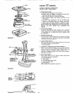
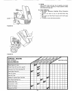
6o V-BELT ADJUSTMENT
A new V-Bett may stretch after the first few hours of opera-
tion resulting in lossof ground speed_
a. To tighten Belt, remove (4) Hex Washer Head Tapping
Screws from Shift Cover Plate (Fig. 48) located on top
of tractor frame• Remove the Cover Plate.
• _ It E li , ,
b. Place Parking Brake Lever in ENGAG D pos=tlon,,
!1
Refer to Stopping Your Tractor page7,,
t*lr. li" , .
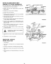
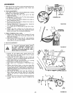
c. Loosen Nut A located on outside of R.H. Chassis
Frame (Fig. 56), slide Take-Up Idler down approximate-
ly 1/2" and tighten Nut "A",
d. Disengage Parking Brake.
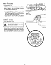
e,, Check position of Clutch Idler Bracket (Fig. 52).
f+ Repeat steps b thru e untd a 1 - 1/t6 dmenson is
obtained between Idler Tab and Frame asshown in Fig
52.
g. Tighten Nut "A" securely.
h, Reinstall Shift Cover Plate and (4) Screws removed in
step a,
- 22-