


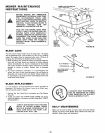

AS NEEDED
1, Make sure all nuts on bolts are tight and cotter pins are se-
cure° Observe all safety precautions, Keep Tractor well
lubricated (refer to page 18),,
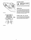
2o TOE-IN ADJUSTMENT
If any parts in Front Axle or Steering Mechanism are being
replaced, Toe-In adjustment is required.
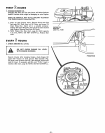
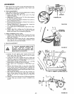
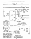
a, Loosen .Jam Nuts (Fig_ 46) at each end of Tie Rod
Adjustment Steeves,
b, Adjust both Tie Rods so that Tie Rod Joints measure
Ii
9- 5/8 from center to center,
c, On front of front tires measure distance from center to
center (measurement No,1}o
d, On rear of front tires measure distance from center to
center (measurement No, 2),
eo Compare measurements - measurement No. 1 should be
1/8- 1/4 less than measurement No. 2,
f, If not adjust each Tie Rod equally to get correct meas-
uremento
g, Tighten Jam Nuts making sure Tie Rod Joints are
parallel (180 °) to each other. This adjustment secures
proper front wheel Toe-In and Steering operat_ono
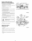
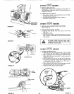
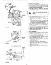
3. CHECK TRANSAXLE OIL LEVEL
a, Remove Filler Plug (Fig, 47) from Transaxieo Oil Level
should be even with Filler Piug threads° Add SoAoE_30
Motor Oii if necessary.
b Check Pressure Relief Valve (Fig, 45 - inset) located on
R.H side near top, It should spring completely closed
when pui{ed out by hand and released.
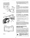
4. BRAKE ADJUSTMENT
_BALL JOINTB_
fJ T,E.oo
(%
"_RUBBER "_
BOOT J
TIE ROD ._..._
\ ADJUSTMENT t \ \
.\ TIE ROD SLEEVE8 _ \\
STEERING LINK
FIGURE 46
• ) TRANSAXLE
.tUG
IF TRACTOR REQUIRES MORE THAN
SIX FEET STOPPING DISTANCE IN
HIGHEST GEAR ON A LEVEL DRY
CONCRETE OR PAVED SURFACE THEN
BRAKE MUST BE ADJUSTED,
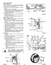
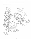
a. Remove (4) Hex Washer Head Tapping Screws from
Shift Cover Plate (Fig, 48), located on top of tractor
frame° Remove the Cover Ptateo
b. Loosen Jam Nut (G) on Brake Rod (B) at Clevis (C)
(Fig. 49). If you find it difficult to loosen Jam Nut (G),
remove Cover Plate in LH, Frame Rail,
c, Rotate Brake Rod (B) counterclockwise, ((-_) turning
Brake Rod out of Clevis (C) four to six turns,
d, Start tractor with Transmission in "NEUTRAL" posi-
tion
e, Depress Brake-Clutch Pedal to the point where Belt
stops moving Hold Brake-Clutch Pedal in position by
engaging Parking Brake If Belt begins to move after en-
gaging Parking Brake, depress Brake-Clutch Pedal to next
notch on Parking Brake.
f, Shut engine off. Rotate Brake Rod (B) clockwise by
hand, turning Brake Rod into Clevis (C), until tight,,
T_ghten Jam Nut (G) on Brake Rod (B) at Clevis (C)
(Fig, 49)°
g, Reinstall Lift Cover Plate and four (4) Mounting Screws,
If Cover Plate was removed in step b it should be re-
placed
FIGURE 47
"5 ...........
C
E
F
- 21 - iFIGURE 49