


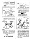
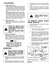

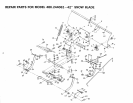

L.H. LIFT PIVOT
MOUNT PLATE
LIFT ASSEMBLY
PIVOT SHAFT
1-1/4" OD SPACER
HITCH BRACE
FIGURE 14
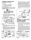
15.
Assemble the other lift pivot plate, over right
hand end of lift assembly pivot shaft and
connect to outside of frame (see figure 15)
using one 3/8" x 1" clevis pin from inside
through front hole in lift pivot plate. Secure with
3/8" flat washer and 3/32"" (small) hairpin
cotter. Secure rear of plate with one 3/8" x 3/4"
clevis pin and one 3/32" (small) hairpin cotter.
Secure ends of pivot shaft to each lift pivot plate
with 1/8" (large) hairpin cotter. See figures 14
and 15.
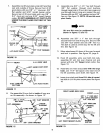
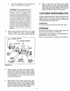
16.
Assemble the front end of each hitch brace
to the rear hole in each hitch plate using one
1/2" x 1-1/4" clevis pin, one 1" OD spacer and
one 1/8" hairpin cotter. See figure 16.
HAIRPIN COTTER
HITCH" PLATE
1" OD SPACER 1/_'; x 1-i/4"
HITCH BRACE CLEVIS PIN
FIGURE 16
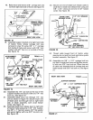
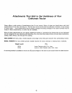
17. Assemble guide bracket assembly shaft end
into the left hand hitch plate. See figure 17. Slide
guide assembly back to the right and into hole
of the right hand hitch plate. Secure with a 1/8"
(large) hairpin cotter in each end. See figure 17.
Lower front end of guide bracket assembly to
straddle channel assembly.
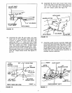
3/32"" 318"" X 3/4'" CLEVIS PINS
HAIRPIN
COTTER-------_ 3/8"
J ._ FLAT WASHER
LI
ROD ,
LIFT ASS'Y. _ LIFT PIVOT
PIVOT SHAFT MOUNT PLATE
RIGHT HAND SIDE VIEW
FRONT --_
FIGURE 15
_ IFRONT PIVOT SHAFT
HITCH ! 1/R-'
PLATE (R.H.) I HAIRPI_I_coTTER
• i
• T
[ / GUIDE BRAICKET ASS,Y.PLATE''/'__'_ ' HITC(L H )
FIGURE 17