


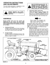

ASSEMBLY INSTRUCTIONS
TOOLS REQUIRED FOR ASSEMBLY
(1) Pliers
(1) Hammer
(1) 7/16" Open End or Box Wrench
(1) 1/2'3 Open End or Box Wrench
(1) 9/16" Open End or Box Wrench
(1) 3/4" Open End or Box Wrench
(1) Adjustable Wrench
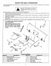
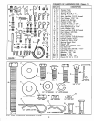
Refer to carton contents figure on page 2 and figure
1 on page 3 for parts and hardware needed to
assemble snow blade.
RIGHT HAND (R.H.) AND LEFT HAND
(L.H.) ARE DETERMINED FROM
OPERATOR'S POSITION WHILE
SEATED ON TRACTOR.
.
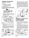
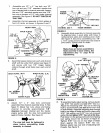
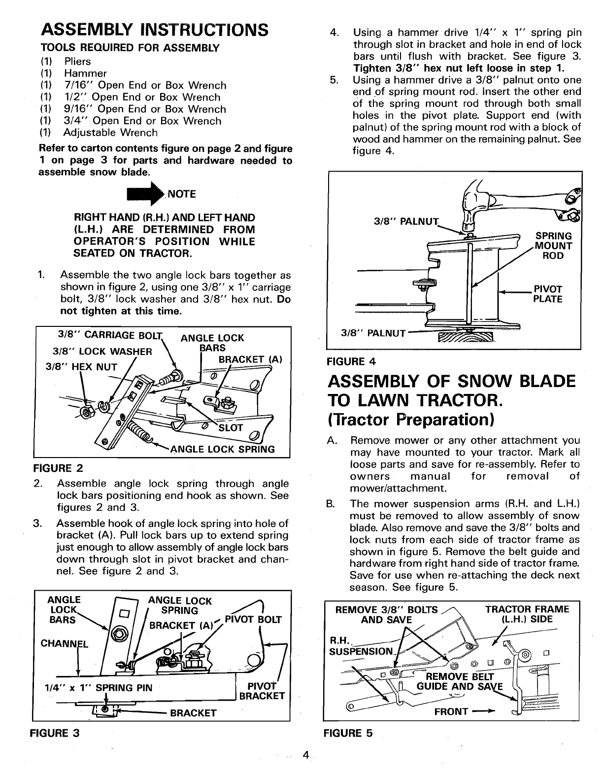
Assemble the two angle lock bars together as
shown in figure 2, using one 3/8" x 1" carriage
bolt, 3/8" lock washer and 3/8" hex nut. Do
not tighten at this time.
3/8"" CARRIAGE BOLT\ ANGLE LOCK
3/8" LOCK WASHER \ BARS
/ _ I BRACKET (A)
3/8" HEX NUT / _ /______/=========_
/'_ "_ANGLE LOCK SP_'NG
FIGURE 2
2. Assemble angle lock spring through angle
lock bars positioning end hook as shown. See
figures 2 and 3.
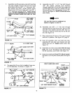
3. Assemble hook of angle lock spring into hole of
bracket (A). Pull lock bars up to extend spring
just enough to allow assembly of angle lock bars
down through slot in pivot bracket and chan-
nel. See figure 2 and 3.
ANGLE ANGLE LOCK
LocK.. 3
BARS _,_ (A). PIVOT BOLT
1/4" x 1" SPRING PIN
=
' _ ' - BRACKET
PIVOT
.
.
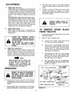
Using a hammer drive 1/4" x 1"' spring pin
through slot in bracket and hole in end of lock
bars until flush with bracket. See figure 3.
Tighten 3/8"" hex nut left loose in step 1.
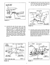
Using a hammer drive a 3/8" palnut onto one
end of spring mount rod. Insert the other end
Of the spring mount rod through both small
holes in the pivot plate. Support end (with
palnut) of the spring mount rod with a block of
wood and hammer on the remaining palnut. See
figure 4.
3,8
.MouNT
3/8" PALNUT =-_=
FIGURE 4
ASSEMBLY OF SNOW BLADE
TO LAWN TRACTOR.
(Tractor Preparation)
A=
g.
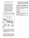
Remove mower or any other attachment you
may have mounted to your tractor. Mark all
loose parts and save for re-assembly. Refer to
owners manual for removal of
mower/attachment.
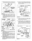
The mower suspension arms (R.H. and L.H.)
must be removed to allow assembly of snow
blade. Also remove and save the 3/8" bolts and
lock nuts from each side of tractor frame as
shown in figure 5. Remove the belt guide and
hardware from right hand side of tractor frame.
Save for use when re-attaching the deck next
season. See figure 5.
REMOVE 3/8"' BOLTS _ TRACTOR FRAME
AND SAVE _ (L.H.) SIDE
/>,.//\\
R.H. __[ _ _---X _-_
_.__UIDE AND SAVE I\ I I
FRONT _
FIGURE 3 FIGURE 5
-- 4,