


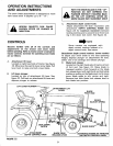


ADJUSTMENT
A.
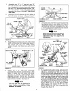
Blade angle lock bars:
Blade angle can be adjusted at the blade pivot
in front of tractor by first raising the blade to
transport position, pull back on angle lock bars
to release the blade and pivot to the right,
center, or left positions. Release lock bars to
lock.
To adjust blade angle from the tractor seat:
Raise blade to transport position. Push forward
on the blade lock release lever (with right foot)
and hold while pushing or pulling on the blade
pivot rod to move snow blade angle to left,
center and right. Remove foot from blade lock
release lever to lock blade into position.
3. DO NOT push snow in the same direction
causing excessive build up with each succesive
pass.
4. If blade is stored in heated area, allow lawn
tractor and blade to adjust to outdoor
temperature before operating to reduce icing on
the metal surfaces.
ALWAYS LOWER BLADE TO
GROUND BEFORE LEAVING
TRACTOR.
B.
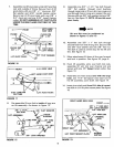
Adjust blade spring:
Blade adjust spring tension is adjustable to
permit blade to tilt forward to by-pass solid
obstructions.
KNOW THE TERRAIN. AVOID
EXCEPTIONALLY SHARP SLOPES OR
DROPOFFS WHICH MAY BE HIDDEN
BY THE SNOW.
NEVER RUN THE SNOW BLADE
INTO HEAVY MATERIAL AT HIGH
SPEED.
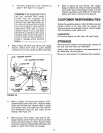
C.
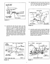
Blade shoe adjustment:
Blade shoes on ends of blade, (see figure 22),
may be raised for close work on smooth sur-
faces or lowered to raise the blade to work on
rough or uneven areas. Make sure both shoes
are set evenly and nuts are tightened securely.
_NOTE
Wheel weights and tire chains must
be used with your snow blade for
traction. These accessories are
available at your nearest Sears retail
or catalog store. See page 12.
OPERATION
.
.
INSPECT THE AREA TO BE WORKED
CAREFULLY BEFORE OPERATING
THE SNOW BLADE. AVOID PIPES,
ROOTS, CURBS'OR OTHER HEAVY
OBSTRUCTIONS.•
Prepare lawn tractor engine for cold weather
use following instructions furnished with lawn
tractor.
Always begin with transmission in first (low)
gear and gradually increase speed as required.
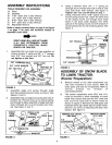
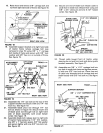
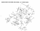
TO REMOVE SNOW BLADE
FROM TRACTOR
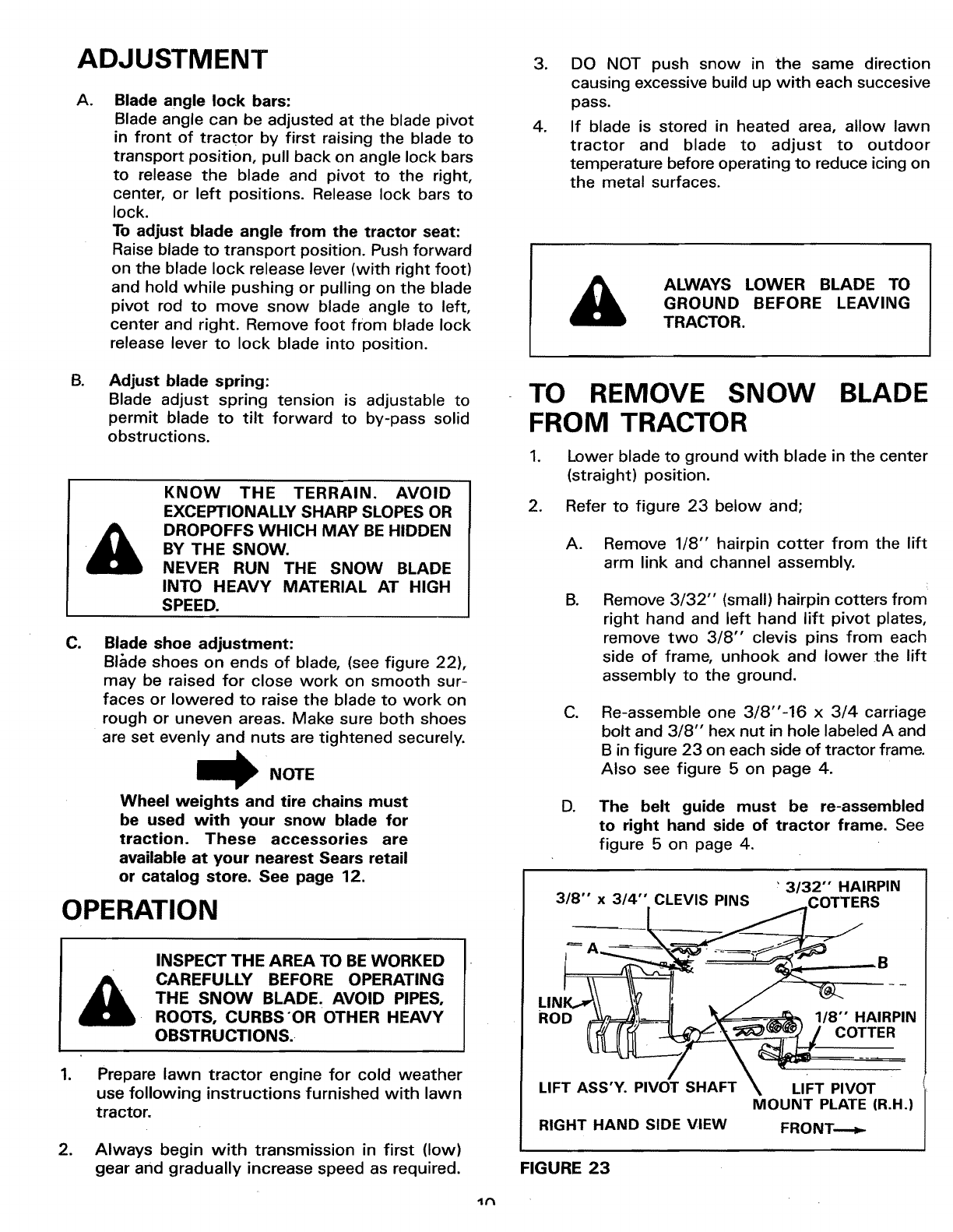
1. Lower blade to ground with blade in the center
(straight) position.
2. Refer to figure 23 below and;
A.
B.
Remove 1/8" hairpin cotter from the lift
arm link and channel assembly.
Remove 3/32" (small) hairpin cotters from
right hand and left hand lift pivot plates,
remove two 3/8" clevis pins from each
side of frame, unhook and lower the lift
assembly to the ground.
C.
Re-assemble one 3/8"-16 x 3/4 carriage
bolt and 3/8" hex nut in hole labeled A and
B in figure 23 on each side of tractor frame.
Also see figure 5 on page 4.
D. The belt guide must be re-assembled
to right hand side of tractor frame. See
figure 5 on page 4.
3/32'" HAIRPIN
MOUNT PLATE (R.H.I
RIGHT HAND SIDE VIEW FRONT----_
FIGURE 23
lt"t