


15
SERVICE & ADJUSTMENTS
tightening the set screw.
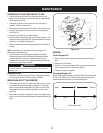
TIRES
Themaximumpressureforthetiresis30psi.Donotexceedthe
manufacturer’s recommended psi under any circumstances. Maintain
equal pressure on all tires.
WARNING
Excessivepressurewhenseatingbeadsmaycausethetire/rim
assemblytoburstwithforcesufficienttocauseseriousinjury.Referto
sidewall of the tire for the recommended pressure.
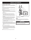
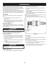
FLEXIBLE PUMP COUPLER
Theflexiblepumpcouplerisanylon“spider”insert,locatedbetween
the pump and the engine shaft. Over time, the coupler will harden and
deteriorate.
Replace the coupler if you detect vibration or noise coming from the
area between the engine and the pump. If the coupler fails completely,
youwillexperiencealossofpower.
IMPORTANT: Never hit the engine shaft in any manner, as a blow will
cause permanent damage to the engine.
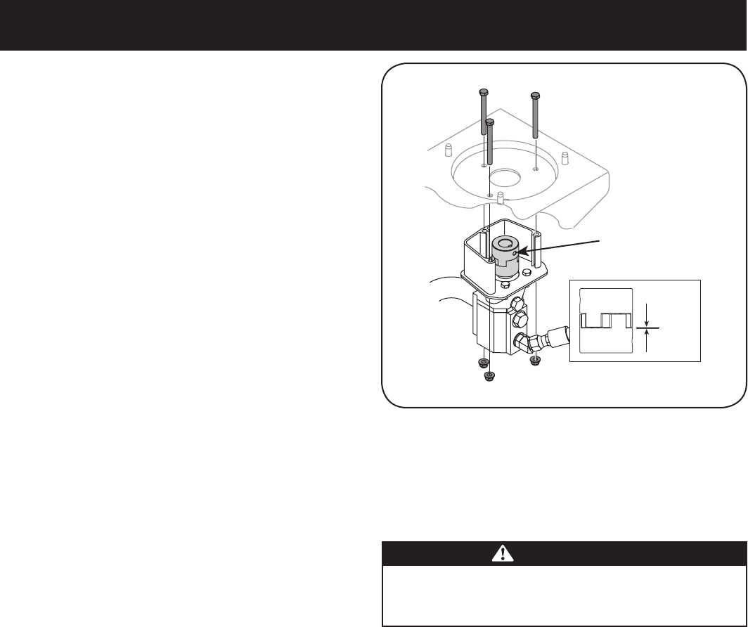
1. Remove the three nuts that secure the pump to the coupling shield.
Two nuts are at the bottom corners and one is in the top center. See
Figure 5-2.
2. Remove the pump.
3. Rotate the engine by slowly pulling the starter handle until the
engine coupling half set screw is visible. Loosen the set screw
using allen wrench and slide the coupling half off the engine shaft.
4. Loosen the set screw on the pump coupling half and remove the
coupling half.
5. Slide the new engine coupling half onto the engine shaft until the
end of the shaft is flush with the inner portion of the coupling half.
(There must be space between the end of the engine support
bracket and coupling half). Tighten the set screw.
6. Install the pump coupling half and key on the pump shaft. Rotate
the coupling half until the set screw faces the opening in the shield.
Do not tighten the set screw.
7. Install the nylon “spider” onto the engine coupling half.
8. Align the pump coupling half with the nylon “spider” by rotating the
engine using the starter handle. Slide the coupling half into place
while guiding three mounting bolts through holes in pump support
bracket.
9. Secure with the nuts removed earlier.
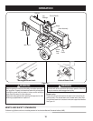
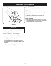
10. Set .010” to .060” clearance/gap between the nylon “spider” and
the engine coupling half by sliding a feeler gauge or matchbook
cover between the nylon “spider” and the engine coupling half and
moving pump coupling half as needed. Secure pump coupling half
with set screw. See Figure 5-2.
NOTE: Make certain the proper clearance/gap is obtained before
Figure 5-2
.0600
.0100
Side View-Coupler
Set Screw