8)
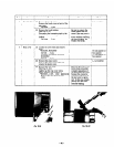
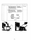
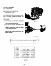
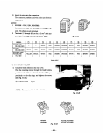
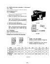
Insert the wires into the connectors.
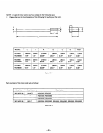
The connector positions and wire colors are shown in
Table 10-3.
NOTES:
1. RGX505 - 1 lOV, 12OV, RGX505D:
Connectors are used for terminals (7) through (101
only. The others are pin terminals
2. Terminals 111 through (61 are for a 2 mm’ wire and
terminals (71 through (10) for a 0, 75mm2 wire.
Fig. lo-25
MODEL
RGX305,405 ’
220,230,24OV ! -
- 1 ’ RED
WHITE BROWN ORANGE WHITE
RED
BROWN
GREEN
RGX505
220,230,24OV
WHITE ] RED
WHITE
RED ’ BROWN ORANGE WHITE , RED
BROWN GREEN
I
I
RGX305D. 405D. I
I
RGX305.405
YELLOW BRACK
I I
WHITE
RED
BROWN ORANGE WHITE ! RED 1 BROWN
GREEN
110,120v
I
I
Table 10-5
10-3-5 BRUSH HOLDER
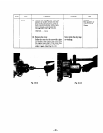
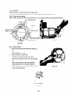
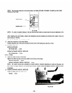
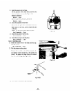
1) Install the brush holders in the rear cover.
Pass the mounting screws through the brush holders,
push the brush holders so that the brushes will be per-
pendicular to the slip rings, and tighten the screws.
(See Fig. 10-26.)
54~~18mmscrew...2pcs.
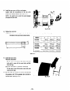
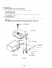
NOTE:
mere
are
two kinds of bursh holders.
Fig. lo-26
RGX305
RGX405, RGX405D
RGX305D
RGX505, RGX505D
Fig. lo-27
-54-


