


9-9 PRIMARY EXCITING CIRCUIT
As described in
5-3 DESCRIPTION of GENERATOR OP-
ERATION,
the primary exciting coil is in the magneto
mounted 0~1 the engine, and the AVR has a circuit for it.
9-9-l EXCITING COIL
The normal inter-terminal resistance of the exciting coil is
about 10 to 30 ohms. Its voltage at the rated rpm is about
AC 10 to 30 V. Check the resistance and voltage with a test-
er to see if they meet these requirements.
9-9-2 OTHERS
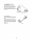
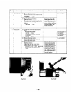
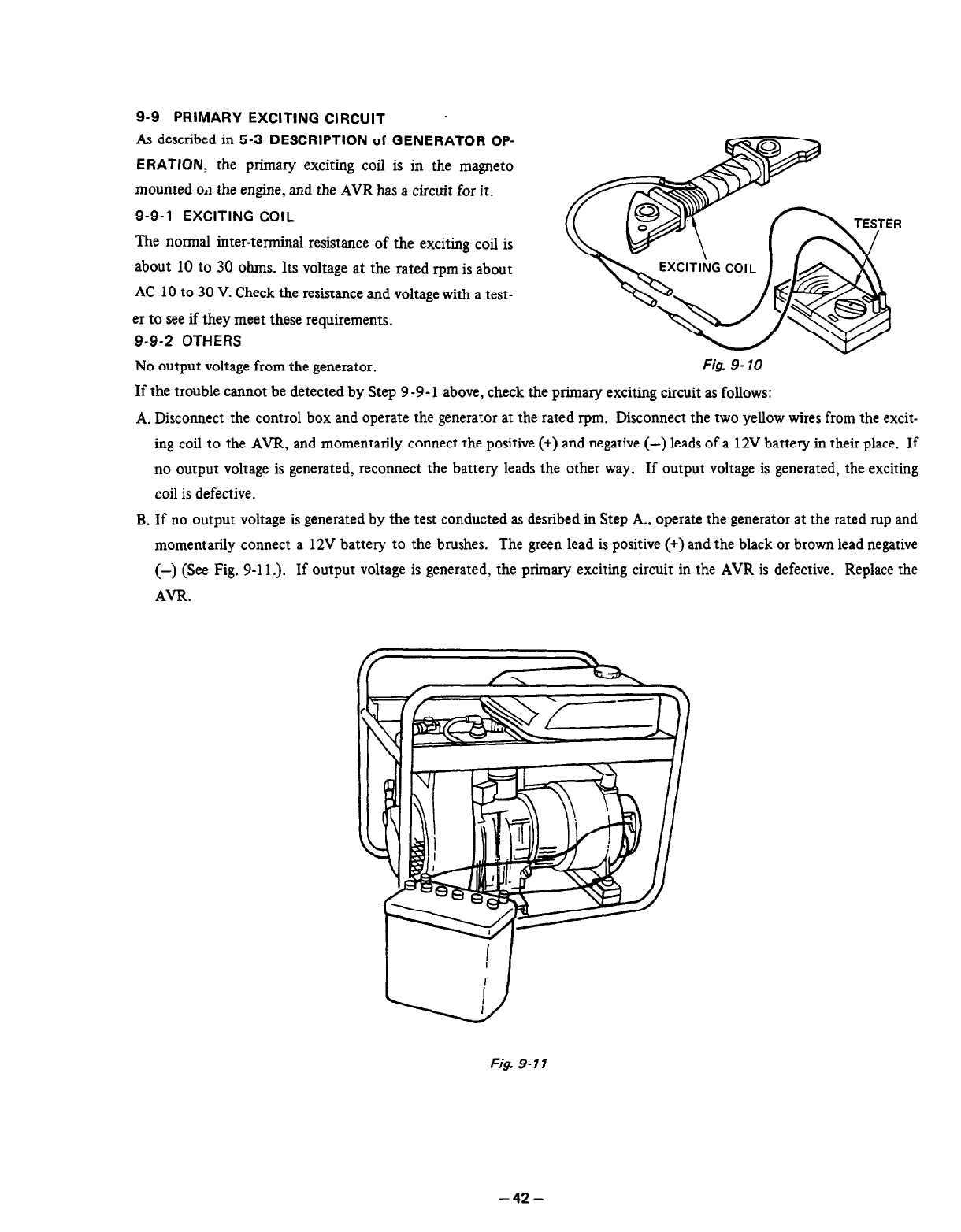
No output voltage from the generator.
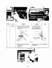
Fig. 9- 10
If the trouble cannot be detected by Step 9-9- 1 above, check the primary exciting circuit as follows:
A. Disconnect the control box and operate the generator at the rated rpm. Disconnect the two yellow wires from the excit-
B.
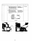
ing coil to the AVR, and momentarily connect the positive (+) and negative (-) leads of a 12V battery in their place. If
no output voltage is generated, reconnect the battery leads the other way. If output voltage is generated, the exciting
coil is defective.
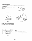
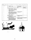
If no output voltage is generated by the test conducted as desribed in Step A., operate the generator at the rated rup and
momentarily connect a 12V battery to the brushes. The green lead is positive (+) and the black or brown lead negative
(-) (See Fig. g-11.). If output voltage is generated, the primary exciting circuit in the AVR is defective. Replace the
AVR.
Fig. 9- 11
-42-