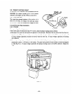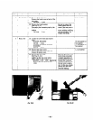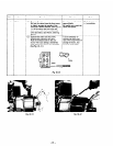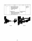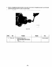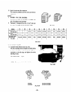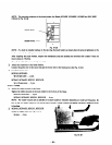
2. Remove a throughbolt and insert the shaft of rotor puller into the hole for throughbolt and push it up till the shaft
reaches the screw hole of the P. T. 0. shaft on the side of engine.
3. As shown in Fig. lo- 16, screw up the bolt pushing the rotor puller shaft and remove the rotor.
Fig. lo-16
1 Order ]
Item
I
Procedure
I
Remarks
I
TOOI
1
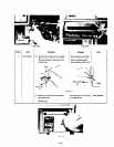
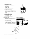
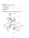
8 ( Front cover (1) Remove the front cover.
I
13 mm box spanner
Remove the bolts that fasten the en-
I
!
gine’s main bearing cover to the front
cover.
I
8@bolt...4pcs.
1
- 50 -


