


RB1 9
CONSTRUCTION OF THE RAT BLASTER:
Sort out your parts to begin with, making sure you have all of the parts required.
You can use old egg cartons to hold various parts to make them easier to find.
We will begin building the kit starting with the lower profile parts to make it
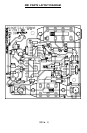
easier for us to mount them. You will want to use the parts layout diagram to
assist you in finding where the components go.
For each part, our word "install" always
means these steps:
1. Pick the correct part value to start with.
2. Insert it into the correct PC board location, making sure the part is
mounted flush to the PC board unless otherwise noted.
3. Orient it correctly, following the PC board drawing and the written
directions for all parts - especially when there's a right way and a wrong
way to solder it in. (Diode bands, electrolytic capacitor polarity, transistor
shapes, dotted or notched ends of IC's, and so forth.)
4. Solder all connections unless directed otherwise. Use enough heat and
solder flow for clean, shiny, completed connections.
❒ 1. Orient the board in the same direction as the parts layout diagram.
❒ 2. Install R6, a 10K ohm resistor (brown-black-orange).
❒ 3. Install R4, a 150K ohm resistor (brown-green-yellow).
❒ 4. Install R5, a 47K ohm resistor (yellow-violet-orange).
❒ 5. Install R7,a 6.8K ohm resistor (blue-gray-red).
❒ 6. Install R2, another 150K ohm resistor (brown-green-yellow).
❒ 7. Install R3, a 100K ohm resistor (brown-black-yellow).
❒ 8. Install R9, a 47K ohm resistor (yellow-violet-orange).
❒ 9. Install R10, a 3.9K ohm resistor (orange-white-red).
❒ 10. Install R8, a 4.7K ohm resistor (yellow-violet-red).