


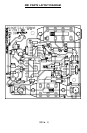


RB1 14
Bend the capacitor over so that it is lying down on the board and solder
both leads (with the cap lying down you should have plenty of room to
solder it in).
❒ 35. Flip the board back over and locate S1, the SPDT power switch. It is
the smaller of the two switches and has six leads. Press it firmly into the
board and solder all six leads.
❒ 36. Install S2, the 3PDT power setting switch. After pushing firmly into the
board, solder all eight connections.
❒ 37. It is now time to install the hookup wire that will connect your completed
board to the speaker. Strip back all four ends of the wire provided about an
eighth of an inch and lightly “tin” them with solder. One pair of ends should
be inserted in the holes next to S2 marked “to speaker”. Solder these wires
to the board. The other ends should be hooked around the tabs on the
speaker and soldered. The speaker has no polarity so the wires can be
hooked up either way.
This completes the assembly of your Rat Blaster! The following steps show you
how to install your kit in the optional case. If you don’t have the case, skip
ahead to the initial testing section.
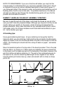
ASSEMBLY INSTRUCTIONS FOR CUSTOM CASE SET
Parts included with the optional custom case set:
❒ 1 case (top and bottom)
❒ 1 Rat Blaster sticker
❒ 6 #6 black 3/8 inch screws
❒ 1 mounting bracket
❒ 1 #20 1/4 inch bolt (for mounting bracket)
❒ Mount the PC board inside the case using two of the #6 screws provided.
❒ Mount the speaker inside the case and attach it using two more #6 screws.
❒ The final two #6 screws are for attaching the top cover to the bottom cover.
You may want to wait until after initial testing to screw the top cover on.
❒ The mounting bracket can be attached once a suitable place is found to
mount your Rat Blaster.