


RB1 13
❒ 23. Install C3, a .1uF disc capacitor (marked .1 or 104).
❒ 24. Install C8, another .1uF disc capacitor (marked .1 or 104).
❒ 25. Install C2, the last .1uF disc capacitor (marked .1 or 104).
❒ 26. It is time to install the transistors, starting with Q3, a 2N3904.
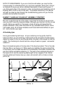
Transistors have three legs and must be mounted correctly. Notice that the
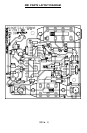
part has a flat side. Orient the flat side as shown on the parts layout. To
install, slide the legs through the circuit board and push the component as
close to the board as possible without straining the leads. Solder all three
connections securely.
❒ 27. Install Q2, a PNP transistor (marked 221334). This transistor and Q1
each appear to have two flat sides. Orient the part using the larger flat side
with no writing on it and install Q2 just as you did Q3 in step 26.
❒ 28. In the same way, install Q1 the other 221334 transistor.
❒ 29. Install Q4 the last transistor, a 2N3904. Watch your orientation.
❒ 30. Before installing the larger parts, we have to install JMP1. From a scrap
component lead, form this jumper and install it as you would a resistor.
Jumpers act like small “bridges” to route traces to the top side of the board
and over obstacles (other traces).
❒ 31. Now we will install the stereo jack, J2. It is located next to JMP1. This
part only fits into the PC board one way and should be placed with the body
of the part as close to the board as possible. Gently bend the tabs over if
necessary to hold the part in place and solder all three connections.
❒ 32. The next part to be installed is J1, the power jack. Press it firmly into the
board and solder all three leads.
There are two components in the center of the PC board that have not been
soldered in yet. Before installing the switches, we will install these parts.
❒ 33. Install D2, the large red LED. Note that one of the two leads is longer.
This is the anode and should be placed in the hole closest to the outline for
C1. Install the part with the leads standing about an eighth of an inch above
the board and solder both legs.
❒ 34. C1, a 330uF electrolytic capacitor, must be installed on the solder side
of the PC board. This part also has a polarity which is marked on the top
side of the board. One side of the capacitor has a stripe which denotes the
negative side, while the PC board silkscreen marks the positive side. Be
sure to orient the part correctly. On the back or solder side of the board,
insert C1’s leads through to the top side, making sure the polarity is right.