


RB1 12
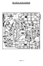
❒ 11. Install D1, the 1N4002 power diode. This diode prevents the possibility
of someone using the incorrect power supply and inadvertently connecting
the power backwards. Make sure the banded end of the diode (cathode) is
installed in the same direction as shown in the parts layout diagram.
❒ 12. Install R16, a 2.2K ohm resistor (red-red-red).
❒ 13. Install R1, a 22K ohm resistor (red-red-orange).
❒ 14. Install R12, R13, R14, and R15 all 6.2 ohm resistors (blue-red-gold).
❒ 15.Install R11, a 10K ohm resistor (brown-black-orange).
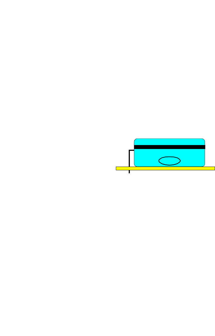
❒ 16. Install C7, one of the 10uF electrolytic capacitors. Make sure to mount
this part in the correct direction! If you look at the component you will see a
stripe down one side, usually indicating the negative (-) terminal of the
component. You will notice on the parts layout diagram that the hole for the
positive terminal is denoted. You will want to install this component with the
positive (+) lead in the same orientation as shown in the parts layout
diagram. If you do not install it correctly, you will end up with all sorts of
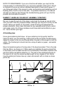
problems in the circuit. Before
soldering, place the leads in the
appropriate holes, then carefully bend
the capacitor over making sure the
leads don’t cross and remain as short
as possible. Then solder the
component.
❒ 17. Install C4, another 10uF electrolytic capacitor using the same procedure
as with C7. Pay close attention to polarity orientation!
❒ 18. Install C6, another 10uF electrolytic capacitor. Make sure that the part is
installed in the correct orientation, bend the component over in the same
orientation as shown in the parts layout diagram, then solder.
❒ 19. Install U1, the NE555 IC. Notice that one end of the chip is marked with
a dot, notch, or band. Be sure to orient this end as shown in the parts layout
diagram and the silkscreen. You may use an IC socket if you wish but be
aware that our technicians see more repair problems due to sockets than
due to chips burned out from overheating with a soldering iron. Be careful
not to “bridge” the pins together.
❒ 20. Install U3, the 4001 IC. Be sure to orient it as shown on the parts layout.
❒ 21. Install U2, an XR-2209 IC, making sure to orient it correctly.
❒ 22. Install C5, a .001uF disc capacitor (marked .001 or 102).
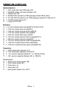
+-20% +-20% +-20% +-20%