


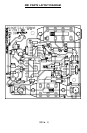


RB1 5
HOW DOES IT WORK?
Here is where we get into a little circuit analysis. If you just want to plug it in and
start scaring off critters, you can skip this section. Otherwise here is some
insight into why and how this RB1 works. We will use the schematic located at
the center of the manual to analyze the circuit.
We will begin with the IC marked NE555, U1. This is a simple, free running
oscillator circuit which is used to generate the lower frequency warble rate of
the signal. This rate varies from around 1Hz to 10Hz. The output of this
oscillator is a 12V square wave until it is sent through R2 into C7. These parts
filter the waveform into a sawtooth waveform.
U2, the XR-2209 is set up to be a voltage controlled oscillator running between
15kHz and 50kHz. The higher the voltage seen on pin 4 of U2, the higher the
frequency produced on pin 7 of U2. When the low frequency sawtooth signal
from U1 is sent to pin 4, the high frequency signal of U2 modulates or “warbles”
at a rate of U1’s output frequency.
S2 controls the average DC voltage of the sawtooth by adjusting the rate of
discharge of C7. The less resistance seen from pin 4 to ground, the faster C7
discharges. The faster C7 is discharged, the lower the average voltage of the
sawtooth waveform is. In turn, the lower the average voltage on the sawtooth,
the lower the average frequency on pin 7 of U2 allowing this unit to cover a
larger area.
The output of U2 is then sent to some logic which enables or disables the
speaker driver circuitry depending on what signal is seen on pin 2 and 6 of U3.
When these pins are at a logic ‘0’, or 0 volts, the transducer driver is enabled,
and when it is ‘1’, or 12 volts, it is disabled.
The speaker driver section consists of a push-pull circuit controlled by U3:D, B,
and C. U3:B inverts the signal from U3:A so that when pin 3 is high (12 volts)
pin 4 is low (0 volts). U3:D and U3:C are set up as inverting buffers to drive the
transistors that drive the transducer.
The speaker driver also consists of the four transistors surrounding SP1 which
provide more power capability than what U3 offers. When U3 pin 11 is high, Q4
is turned on, and Q1 is turned off. This presents about 12 volts on one side of
the transducer. While pin 11 is high, pin 10 is low, which turns on Q2 and Q3
off, pulling the other lead of the transducer to near 0 volts. Now there are
almost 12 volts across SP1, allowing the transducer to produce sound. On the
next half of the cycle, the transistors that were off are turned on, and the ones
that were on are shut off. Now there are 12 volts across the transducer
connected in the opposite direction from before. This is all done at a rate of
around 15,000 to 50,000 times a second, producing the high frequency signal
to scare off the beasties.