


43
Description
0
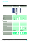
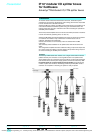
IP 67 modular I/O splitter boxes
for fieldbuses 0
Advantys™
Distributed I/O, FTM splitter boxes
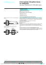
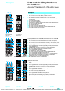
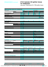
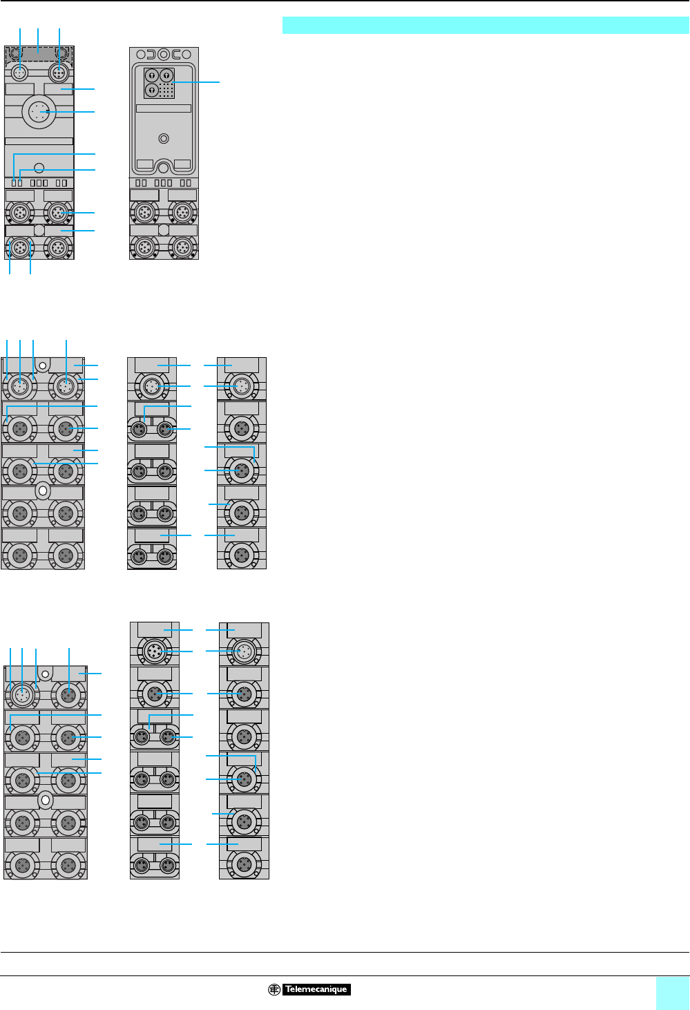
Modular bus modules FTM have the following on the front face:
1 One M12 male connector (bus IN) for connection of the bus.
2 One M12 female connector (bus OUT) for connection of the bus.
3 One 7/8 male connector for connection of the c 24 V power supplies.
4 Four M12 female connectors for connection of the splitter box inputs/outputs via
the internal bus.
5 Four channel marker labels.
6 Two bus module marker labels.
7 Speed selection (CANopen and DeviceNet buses) and bus address switches.
8 One bus power supply status LED.
9 One bus diagnostics LED.
10One sensor power supply diagnostics LED.
11One sensor power supply diagnostics and communication status LED.
12Bus module functional ground connection.
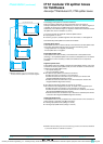
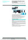
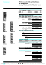
Compact splitter boxes FTM 1Dp08Cpp, FTM 1Dp16C12 and FTM 1Ap04C12p
have the following on the front face:
1 One M12 male connector for connection to the bus module or the previous
module.
2 One M12 male connector for connection of an auxiliary c 24 V actuator power
supply (only applicable to FTM 1DD16C12).
3 Four or eight M12 female connectors (depending on model) for connection of
sensors and actuators.
4 Eight M8 female connectors for connection of sensors and actuators.
5 One or two splitter box marker labels (depending on model).
6 Four or eight channel marker labels.
7 One actuator power supply diagnostics LED.
8 One sensor power supply diagnostics and communication status LED.
9 Four or eight channel status indicator lights (00 to 07).
10Four or eight channel status indicator lights (10 to 17) or channel diagnostic
indicator lights (00 to 07) depending on the splitter box configuration.
11Eight channel “power on” indicator lights (00 to 07).
12One auxiliary supply “power on” indicator light.
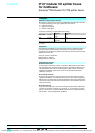
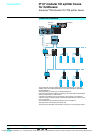
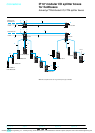
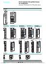
Expandable splitter boxes FTM 1Dp08CppE and FTM 1 Dp16C12E have the
following on the front face:
1 One M12 male connector for connection to the bus module or the previous
module.
2 One M12 female connector for chaining the internal bus to the next module.
3 Four or eight M12 female connectors (depending on model) for connection of
sensors and actuators.
4 Eight M8 female connectors for connection of sensors and actuators.
5 One or two splitter box marker labels (depending on model).
6 Four or eight channel marker labels.
7 One actuator power supply diagnostics LED.
8 One sensor power supply diagnostics LED.
9 Four or eight channel status indicator lights (00 to 07).
10Four or eight channel status indicator lights (10 to 17) or channel diagnostic
indicator lights (00 to 07) depending on the splitter box configuration.
11Eight channel “power on” indicator lights (00 to 07).
Description
1
10 11
12 2
3
8
9
6
7
5
4
Bus module FTM
with cover
Bus module FTM
without cover
1 2
6
6
3
5
3 4
5
1
8
7
12
10
9
11
9
10
FTM 1Dp16C12
FTM 1D
p08C08
FTM 1D
p08C12
FTM 1A
p04C12p
1 2
6
5
3
4
2
5
6
3
1
8
7
10
9
11
9
10
FTM 1Dp16C12E
FTM 1D
p08C08E
FTM 1D
p08C12E
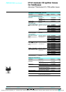
Presentation, functions:
pages 36 - 41
Connections:
pages 44, 45
Characteristics:
pages 46, 47
References:
pages 48, 49
Dimensions, schemes:
pages 50, 51
Courtesy of Steven Engineering, Inc. ● 230 Ryan Way, South San Francisco, CA 94080-6370 ● General Inquiries: (800) 670-4183 ● www.stevenengineering.com