


21
Description,
configuration
0
IP 67 monobloc I/O splitter boxes
for fieldbuses 0
Advantys™
Distributed I/O, FTB splitter boxes
Profibus™-DP bus
Description
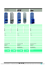
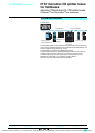
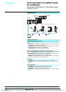
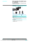
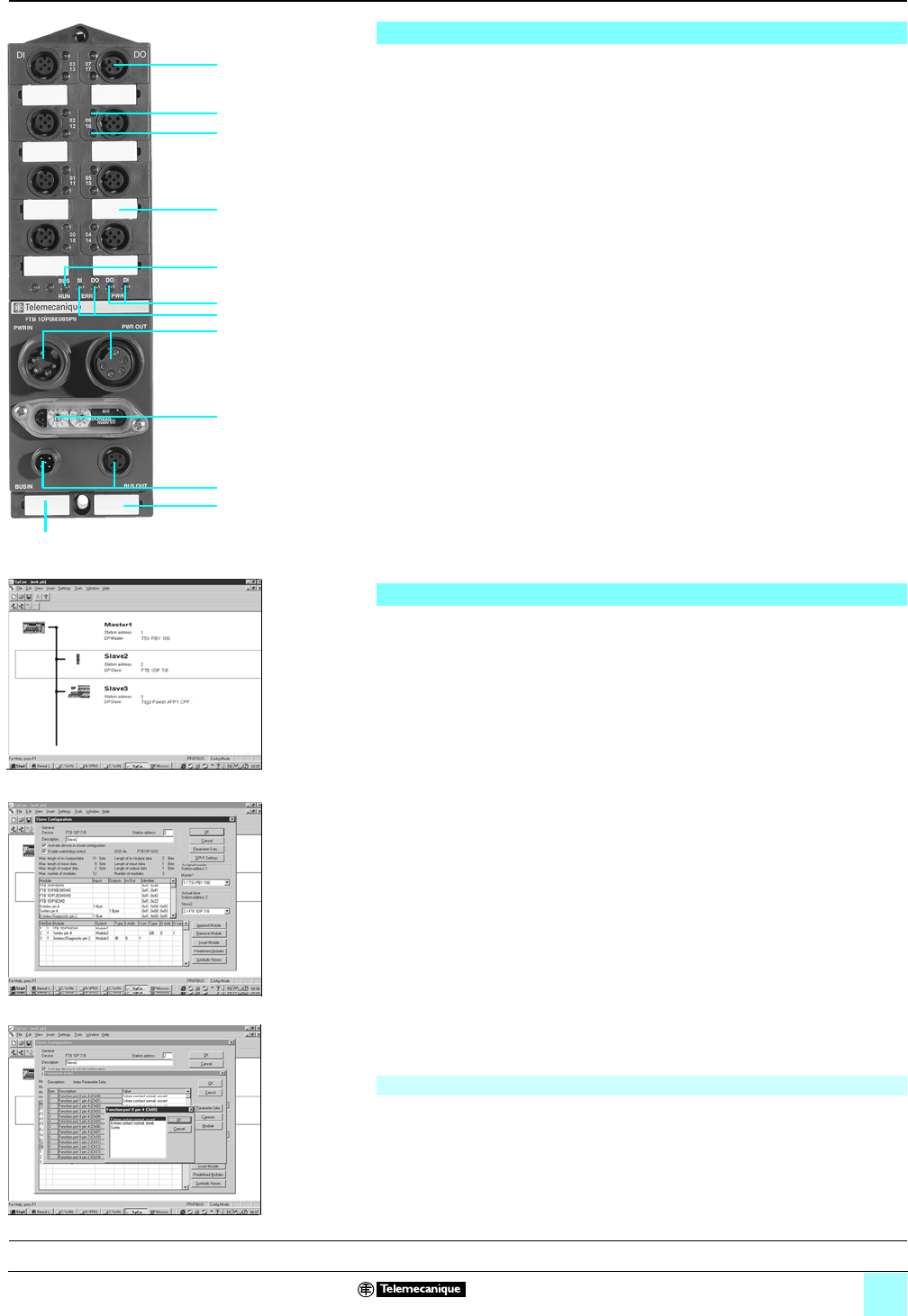
Profibus-DP monobloc I/O splitter boxes FTB 1DP have the following on the front
face:
1 Eight M12 female connectors for connection of sensors and actuators (2 channels
per connector).
2 Eight channel status indicator lights (00 to 07).
3 Eight channel status indicator lights (10 to 17) or channel diagnostic indicator
lights (00 to 07) depending on the splitter box configuration.
4 Two 7/8 connectors for connecting the c 24 V sensor and actuator power
supplies: male for PWR IN, female for PWR OUT.
5 One M12 male connector (bus IN) and one M12 female connector (bus OUT) for
connection of the Profibus-DP bus.
6 Access to the address coding wheels.
7 One bus diagnostics LED.
8 Two sensor/actuator diagnostic LEDs.
9 Two c 24 V sensor and actuator supply status LEDs.
10Eight channel marker labels.
11Two splitter box marker labels.
12Splitter box functional ground connection (beneath the label).
Configuration
The Profibus-DP identification number is a preset, non-modifiable element exclusive
to each Slave.
An .gsd file is assigned to each product, which contains all the important information
relating to the product. An icon (.dib for Profibus-DP) is also available for installation
in the system configurator (please refer to the configuration software documentation
for the import of .gsd files).
During configuration of the equipment, the Master receives precise criteria relating to
the overall structure of the fieldbus via the system configurator. All necessary
information relating to the type and operational behavior of the various Slaves, as
well as data concerning the identification number, is included in the .gsd file.
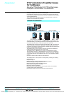
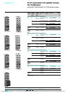
Example with SyCon configurator (refer to our Modicon
®
Premium
™
PLC automation
platform catalog):
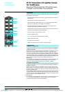
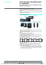
b Select the products for the application from the product catalog library in the
SyCon software (step 1),
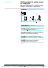
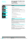
b Product configuration (step 2):
d double-click on the product icon to access the product configuration menu,
d select the required product reference from the suggested list,
d select the associated functions that you wish to use with the product.
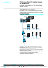
b Channel by channel, configure the type of signal that will be connected to it
(step 3):
d input (N/O or N/C contact),
d diagnostic input (only applicable to channels 10 to 17),
d output.
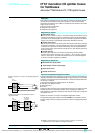
Addressing
For the Slaves, the assignment of addresses generally starts at address 3 (0-2
reserved for the Master). The addresses are configurable from 1 to 99 by means of
2 coding wheels (x 10 and x 1).
1
2
3
6
4
5
11
7
9
8
10
108734
562014
Step 1: Product selection
562015
Step 2: Access to the configuration menu
562016
Step 3: Configuration
Presentation, functions:
pages 14 - 17
Characteristics:
pages 26, 27
References:
pages 28 - 30
Dimensions:
pages 31 - 33
12
Courtesy of Steven Engineering, Inc. ● 230 Ryan Way, South San Francisco, CA 94080-6370 ● General Inquiries: (800) 670-4183 ● www.stevenengineering.com