37
Presentation (continued)
0
IP 67 modular I/O splitter boxes
for fieldbuses 0
Advantys™
Distributed I/O, FTM splitter boxes
c
DESINA - Standard relating to the connector technology of sensors, and actuators, established
by the German Machine Tool Builder’s Association.
Presentation (continued)
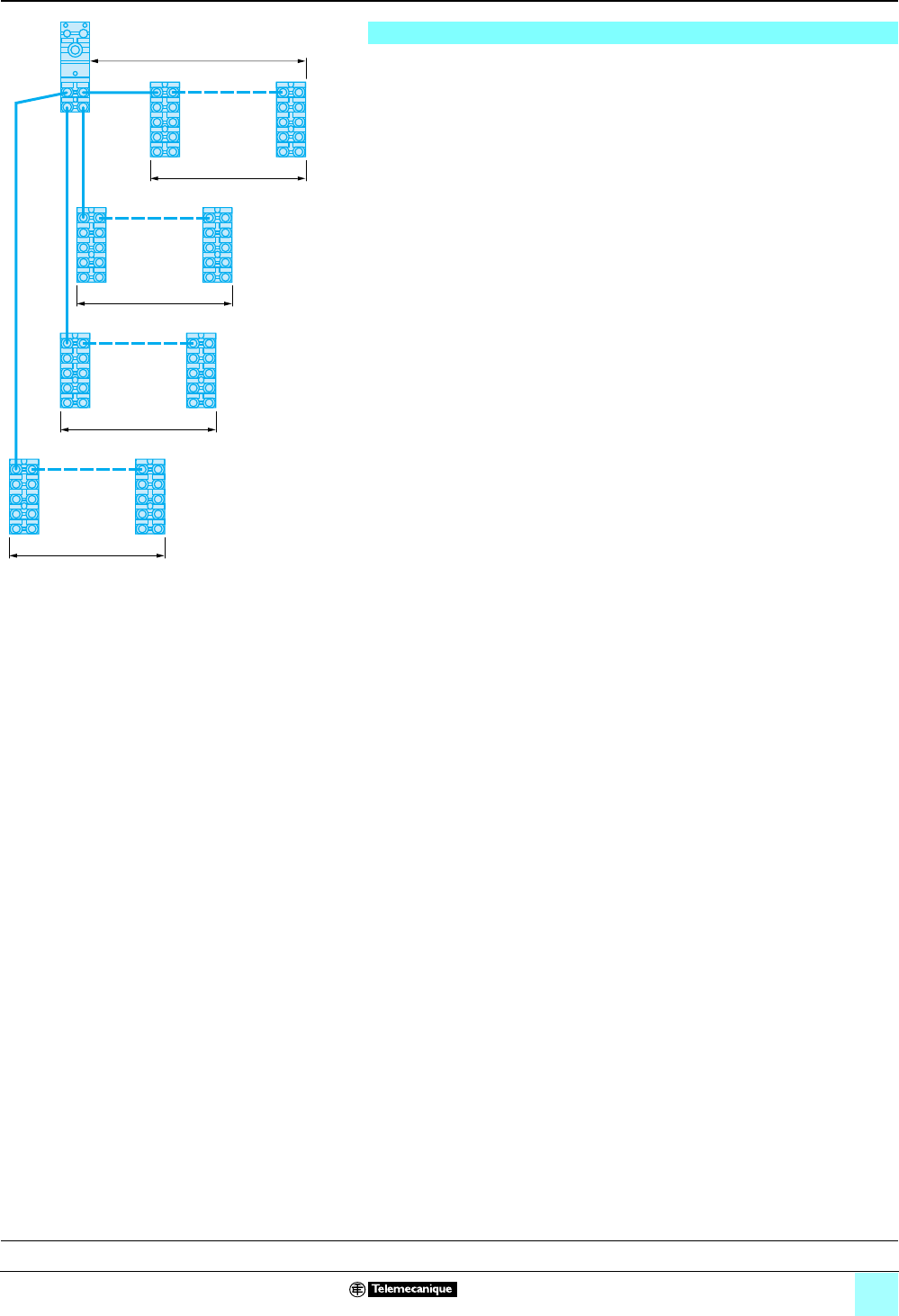
The topology of the system is a star/line architecture.
Each bus module is fitted with four M12 connectors for the connection of
Advantys FTM splitter boxes (star architecture). On each “run”, called a segment, it
is possible to connect up to 4 splitter boxes on the chaining principle (line
architecture). The maximum length of a segment, between the bus module and the
last splitter box, must not exceed 5 m (16.4 ft.).
For one bus module, the maximum number of splitter boxes is:
b 4 per segment, i.e. 64 I/O.
b 16 for the group of 4 possible segments of the bus module, i.e. 256 digital I/O.
Several Advantys FTM splitter box variants are available:
Compact splitter boxes
These splitter boxes do not allow continuity of the internal bus to other splitter boxes
on the same bus module segment. They are used in the following cases:
- a single splitter box on a segment (no chaining),
- the last splitter box on a segment.
Expandable splitter boxes
These splitter boxes allow continuity of the internal bus to other splitter boxes
(chaining). If an expandable splitter box is used as the last splitter box of an internal
bus segment, it is then necessary to install a line terminator on the output bus
connector.
Digital I/O splitter boxes
These splitter boxes are available in compact and expandable versions, only for the
connection of sensors (input splitter boxes) or for the connection of sensors and/or
actuators (input/output splitter boxes):
- c 24 V inputs, IEC type 2.
- c 24 V 0.5 A transistor outputs.
b The different input splitter box variants are as follows:
v8 x M8 connectors for connection of up to 8 sensors,
v4 x M12 connectors for connection of up to 8 sensors (4 for sensors with
integrated DESINA c diagnostics function),
v8 x M12 connectors for connection of up to 16 sensors (8 for sensors with
integrated DESINA diagnostics function).
b The different input/output splitter box variants are as follows:
Each channel can be configured as an input, an output or as a diagnostic input.
v8 x M8 connectors for connection of up to 8 sensors or actuators,
v4 x M12 connectors for connection of up to 8 sensors or actuators (4 for sensors
with integrated DESINA diagnostics function),
v8 x M12 connectors for connection of up to 16 sensors or actuators (8 for sensors
or actuators with integrated DESINA diagnostics function).
Analog I/O splitter boxes
These splitter boxes are only available in the compact version for the connection of
analog sensors or actuators using M12 connectors:
b 4 analog input splitter boxes (voltage or current).
b 4 analog output splitter boxes (voltage or current).
5 m (16.4 ft.) max. (1)
4 splitter boxes max.
4 splitter boxes max.
4 splitter boxes max.
4 splitter boxes max.
Segment 1
(1)Maximum distance of 5 m (16.4 ft.) between the bus
module and the last splitter box on the same segment.
Segment 2
Segment 3
Description:
page 43
Connections:
pages 44, 45
Characteristics:
pages 46, 47
References:
pages 48, 49
Dimensions, schemes:
pages 50, 51
Segment 4
Courtesy of Steven Engineering, Inc. ● 230 Ryan Way, South San Francisco, CA 94080-6370 ● General Inquiries: (800) 670-4183 ● www.stevenengineering.com


