


Page 26
January 28, 2008
Quadra-Fire · Sapphire · 250-7233F
•
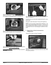
A small amount of air will be in the gas supply lines. When
fi rst lighting appliance it will take a short time for air to
purge from lines. When purging is complete the appliance
will light and operate normally.
Air only needs to be purged again if gas valve has been
turned to the OFF position.
WARNING
Fire hazard.
Do NOT change the valve settings.
• This valve has been preset at the factory.
• Changing valve settings may result in fi re
hazard or bodily injury.
WARNING
Fire or Explosion Hazard
• Gas build-up during line purge may ignite.
• Purge should be performed by qualifi ed technician.
• Ensure adequate ventilation.
• Ensure there are no ignition sources such as
sparks or open fl ame.
WARNING
CHECK FOR GAS LEAKS
Explosion Risk
Fire Risk
Asphyxiation Risk
• Check all fi ttings and connections.
• Do not use open fl ame.
• After the gas line installation is complete, all
connections must be tightened and checked
for leaks with a commercially-available,
non-corrosive leak check solution. Be sure
to rinse off all leak check solution following
testing.
Fittings and connections may have loosened
during shipping and handling.
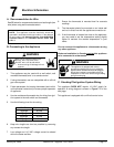
Omni-Test Laboratories listed gas appliances are tested
and approved without requiring changes for elevations
from 0 to 2000 feet in the U.S.A. and 0 to 4500 feet in
Canada.
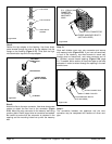
When installing this appliance at an elevation above 2000
feet, it may be necessary to decrease the input rating by
changing the existing burner orifi ce to a smaller size. Input
rate should be reduced by 4% for each 1000 feet above a
2000 foot elevation in the U.S.A. If the heating value of the
gas has been reduced, these rules do not apply. To identify
the proper orifi ce size, check with the local gas utility.
If installing this appliance at an elevation above 4500 feet
(in Canada), check with local authorities.
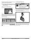
NOTE: A listed (and Commonwealth of Massachusetts ap-
proved) 1/2 inch (13mm) T-handle manual shut-off valve and
fl exible gas connector are connected to the 1/2 inch (13mm)
control valve inlet.
• If substituting for these components, please consult local
codes for compliance.
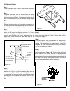
NOTE: The gap between the supply piping and gas access
hole may be plugged with non-combustible insulation to prevent
cold air infi ltration.
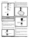
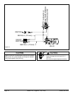
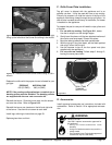
C. Gas Connection
NOTE: Have the gas supply line installed in accordance with
local building codes, if any. If not, follow ANSI Z223.1. Instal-
lation should be done by a qualifi ed installer approved and/or
licensed as required by the locality. (In the Commonwealth of
Massachusetts, installation must be performed by a licensed
plumber or gas fi tter.)
Leak test all gas line joints and the gas control valve prior
to and after starting the fi replace.
Before making the gas connection, ensure that the appliance
you are installing is designed for the type of gas being
supplied. This information can be found on the Ratings Label
under the appliance. If the appliance has been converted to
propane (LP), the valve cover should have a label stating
that the unit has been converted to propane.
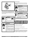
Connect the gas line at the 3/8 in. (9.5mm) pipe connector
on the valve at the back of appliance. We recommend
connecting the appliance with an approved flex gas line.
If flex gas lines are not approved in your area, you must
connect a hard pipe to the gas hookup.
You must supply a manual shut-off valve in a visible location
within 3 ft. (914mm) of the appliance.
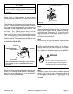
WARNING
Gas Leak Risk.
• Support control when attaching pipe to
prevent bending gas line.