


January 28, 2008
Page 11
Quadra-Fire · Sapphire · 250-7233E
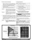
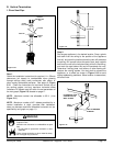
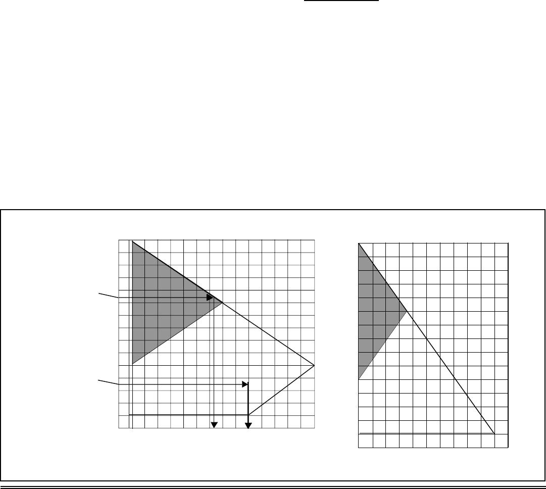
D. How to Use the Vent Graph E. Venting Guidelines
NOTE: IF YOUR INSTALLATION FALLS WITHIN A
SHADED AREA ON THE GRAPH, THE DAMPER MUST
BE USED.
NOTE: In the Commonwealth of Massachusetts, the word
damper shall be replaced with the words flue restrictor.
1. Measure the distance from the top of appliance to the
center of the 90° elbow. On the graph below, draw a
horizontal line from that measurement on the vertical
axis across until it intersects with the slanted line.
2. From the point of this intersection, draw a vertical line to
the bottom of the graph.
3. The point at which this line meets the bottom line of the
graph is the maximum length of the horizontal run.
Example 1: If the vertical dimension from the top of the
appliance to the center of the 90° elbow is
7 ft. (2m), the horizontal run to the base of
the temination cap must not exceed 13 ft.-
2 in. (4m).
Example 2: If the vertical dimension from the top of the
appliance is 21 ft. (6m), the horizontal run
to the base of the termination cap must not
exceed 7 ft.- 3in. (2m).
Example: The use of 3 elbows would reduce the
allowable horizontal run to 9 ft. (3 - 1 =
2 elbows x 3 ft. = 6 ft.; 15 ft. max. - 6 ft.=
9 ft. max.)
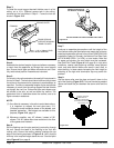
4. Each 90° elbow is equivalent to 3 ft. (914mm) of vent
pipe and each 45° elbow is equivalent to 1 ft. (305mm)
of vent pipe, and must be subtracted from vent pipe
run. A single vertical to horizontal 90° elbow is already
calculated into the allowable 15 ft. (5m) run. Each
additional 90° elbow reduces the maximum horizontal
distance by 3 ft. (914mm).
Notes: The maximum horizontal vent run is 15 ft. (5m)
when the vertical vent rise is 10 ft. (3m).
The minimum horizontal vent run is 11 in.
(279mm).
Minimum wall thickness is 4 in. (102mm). Maximum
wall thickness is 20 in. (508mm).
Horizontal sections require a 1/4 in. (6mm) rise for
every 12 in. (305mm) of horizontal travel.
Exterior Vent Diameter = 6-5/8 in. (168mm); Inner
Vent Diameter = 4 in. (101mm).
Horizontal sections require noncombustible support
every 3 ft. (914mm), e.g. plumbing tape.
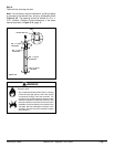
EXCEPTION FOR REAR VENT KIT (Snorkel Kit
#844-8921), HORIZONTAL INSTALLATION:
When installing the Sapphire in a rear vent configuration
with no vertical rise: a snorkel kit must be used, and
a derating orifice must be installed. The appropriate
orifice is supplied with the rear vent kit.
For any vertical rise when rear venting, a minimum of 2
ft. (610mm) vertical must be used prior to any horizontal
run.
The maximum horizontal vent run is 2 ft. (610mm).
The maximum horizontal vent run with a 45° elbow is 14
in. (356mm).
No external minimum rise is required. The minimum
horizontal vent run is 11 in. (279mm).
Figure 5.2
TOTAL HORIZONTAL RUN TO BASE OF THE
TERMINATION CAP (EXCLUDING ELBOWS)
EX. 2
EX. 1
11" 2' 4' 6' 8' 10' 12' 14' 15'
30'
28'
26'
24'
22'
20'
18'
16'
14'
12'
10'
8'
6'
4'
2'
0'
(MAX)
(MIN)
TOP VENT GRAPH
REAR VENTING WITH VERTICAL RISE
2' 4' 6' 8' 10'
30'
28'
26'
24'
22'
20'
18'
16'
14'
12'
10'
8'
6'
4'
2'
0'
(MAX)
(MIN)
VERTICAL DISTANCE
FROM APPLIANCE
TOP TO 90° ELBOW