


January 28, 2008
Page 21
Quadra-Fire · Sapphire · 250-7233E
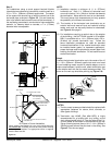
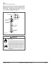
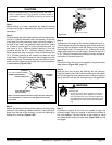
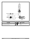
10 in. x 10 in. (254mm x 254mm)
FRAMED OPENING IN WALL
STUDWALL
MASONRY
CHIMNEY
RETRO CONNECTOR
FOUR MASONRY BOLTS
(NOT INCLUDED)
WALL THIMBLE
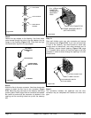
COVER
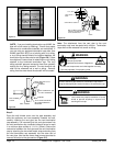
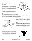
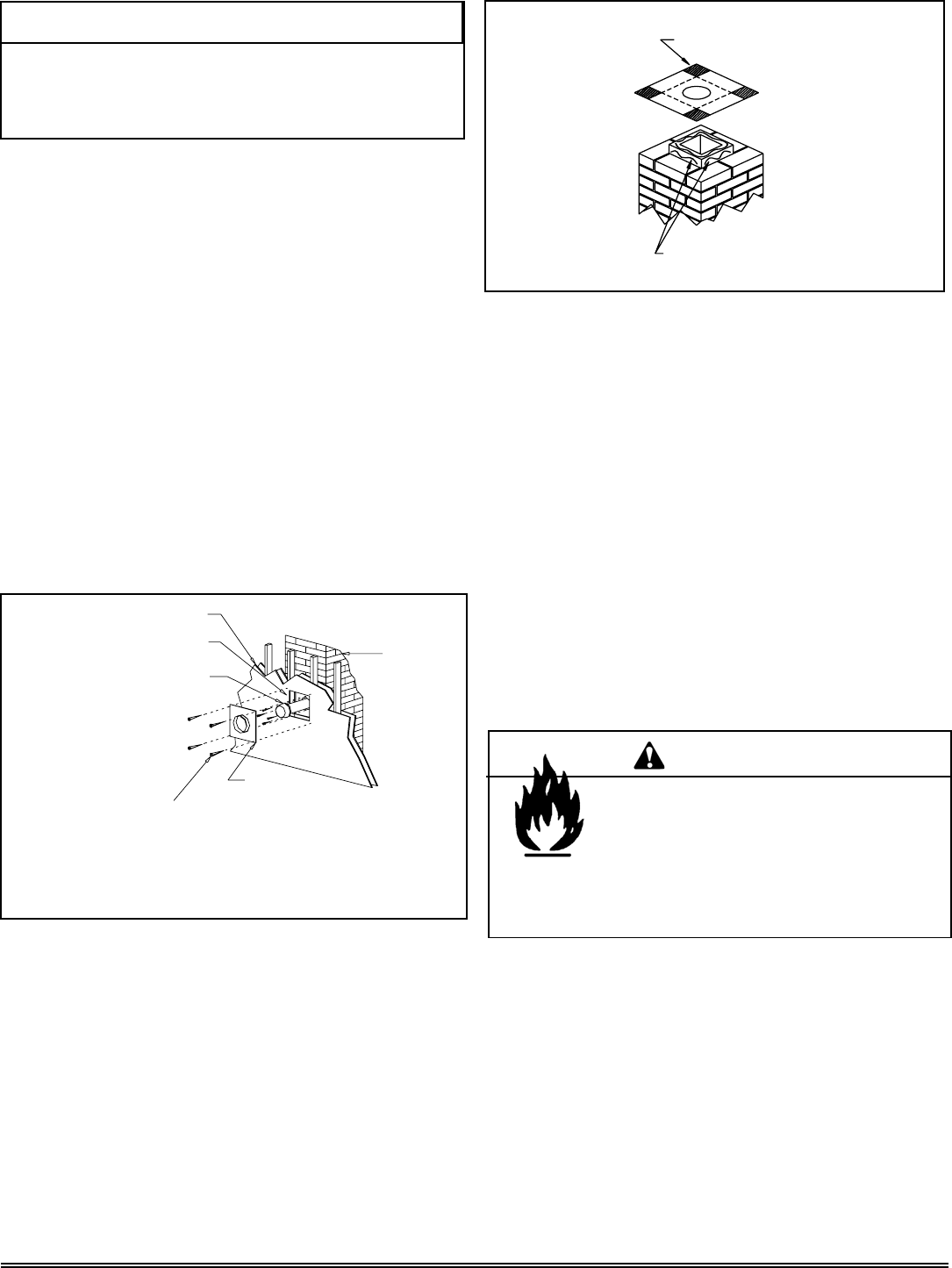
CUT AND BEND FLASHING AS
NEEDED TO FIT CHIMNEY
SEALANT-ADHESIVE
Figure 5.24
Figure 5.25
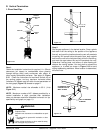
Step 1.
Before cutting any holes, assemble the desired sections
of direct vent pipe to determine the center of the masonry
penetration.
Step 2.
Once the center point of the penetration has been determined,
cut a 6 in. (152mm) diameter hole in the masonry. If the hole
is too large, the retro connector might not mount properly; if
the hole is too small, the appliance might starve for intake
air. If there is a frame wall in front of the masonry wall, cut
and frame a 10 in. (254mm) square opening in the wall
(centered around the 6 in. (152mm) masonry opening). If
there is sheet rock only (no studs) in front of the masonry the
10 in. (254mm) opening is still needed, but does not need
to be framed. If the hole is framed a round support box/wall
thimble is required. This allows the retro connector to mount
directly on the masonry and provide the correct clearances
to combustibles (Figure 5.24).
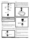
Step 4.
To determine the length of flex needed, measure from 3 in.
(76mm) above the top of the flashing down to the level of the
opening. Add the distance from the center of the chimney
out through the wall. Cut a piece of 4 in. (102mm) flex to this
length (extended to its nominal length). Be sure to leave 2-3
in. (51-76mm) of flex above the existing chimney to allow for
connection to the termination kit.
Step 3.
Secure the flashing to the top of the masonry chimney using
a bead of non-hardening sealant-adhesive. If the flashing is
larger than the top of the chimney, cut and fold flashing as
needed to fit chimney (Figure 5.25).
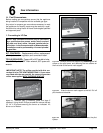
Step 5.
Connect the flex liner to the top adapter using three sheet
metal screws (Figure 5.20, page 19).
Step 6.
Feed the flex liner through the flashing into the chimney.
Carefully feed the flex liner down the chimney to the bottom
and out the opening in the masonry wall, forming an angle to
line up the flex liner with the vent opening on the appliance.
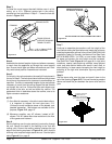
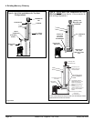
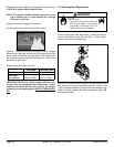
Step 7.
If additional lengths of flex liner are needed to span the
chimney height, use a flex coupler to connect the pieces of
flex liner together. Connect the flex to the coupler by using
four sheet metal screws for each side (Figure 5.26, on the
next page).
Fire Risk.
Explosion Risk.
• Do not let the fl ex liner sag below the level at
which it will connect to the appliance or connector.
This could allow hot gas to become trapped and
potentially become a fi re hazard. The fl ex liner path
should always be sloped up toward the termination
cap.
WARNING
NOTE: For hearth applications refer to page 19, Figure 5.23 for the
use of the 923GCL co-axial to co-linear appliance connector.
CAUTION
Ensure that existing chimney is functionally sound and clean.
• Have inspection done by qualified chimney sweep or
professional installer BEFORE converting to direct vent
appliance.