


10
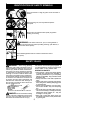
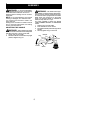
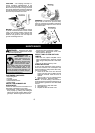
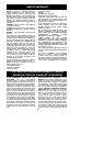
Air Filter Cover
Air Filter
Button
MUFFLER AND SPARK ARREST-
ING SCREEN
WARNING: The muf fler on this prod-
uct conta ins chemicals known to the State of
California to ca use cancer.
As your unit isused , carbondepositsbuild up
on the muffler and spark arresting screen.
For normal hom eowner use, h owever , the
muffler andspar k a rresting scr eenwillnot re-
quire any service. After 50 hours of use, we
recommend that your m uffler be servi ced or
replaced by your authorized servi ce dealer.
REPLACE SPARK PLUG
Replace the spark plug each year to ensure
the engine starts easier and runs better. Set
spark plug gap at 0.025 inch (0.6 mm). Igni-
tion t im ing is fixed and nonadjustable.
NOTE: This sp ark ignition system complies
with the Canadian st andard ICES--002.
1. T wist, then pull off spark plug boot.
2. Remove spark plug from cylinder and dis-
card .
3. Replace wit h Champion RCJ-6Y spark
plug and tighten securely with a 3/4 inch
(19 mm) socket wrench.
4. Reinst all the spark plug boot.
SERVICE AND ADJUSTMENTS
LINE REPLACEMENT
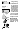
1. Remove spool by firmly pulling on tap
button.
2. Clean entire sur face of hub and spool.
3. Replace with a pre-wound spool, or cut
two lengths of
12-1/2 feet (3.8 meters) of
0.080 inch (2 mm) diameter Poulan/
WEED EATER b rand line.
WARNING: Ne ver use wire, rope,
string,etc., whichcanbreakoffandbecomea
dangerous missile.
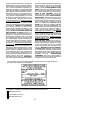
4. Insert ends of the lines about 1/2 inch (1
cm) into the small holes on the inside of
spool.
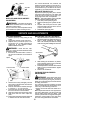
Small
Holes
Spool
Hub
Line in Notch
Line in Notch
Line exit holes
5. Wind the line evenly and tightly onto the
spool. Wind in the directionof thearrows
found on the spool.
6. Pushthe lines intothenotches, leaving 3
to 5 inches (7 -- 12 cm) unwound.
7. Insert the lines into the the exi t holes in
the hub as shown in the illustrat ion.
8. Align the notches with the line exit holes.
9. Push spool into hub until it snaps into
place.
10. Pull thelines extendingoutsideof thehub
to release the lines from the notches.
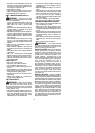
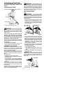
REPLACING THE CUTTING HEAD
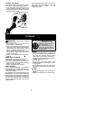
1. Align h ole i nthe dustcupwith theholeinthe
side ofth e gearbox b y rotating thedustcup.
2. In se rt a small screwdri ve r into ali g n e d
holes. This will keep the shaft fro m turn ing
while removin g a nd installing tr immer head.
Screwdriver
3. While holding the screwdriver in posi tion,
remove trimmer head by turning clockwise
(looki ng from bottom of unit).
4. Thread replacement trimmer head onto t he
shaft by tur ning co untercl ockwise. Tighten
until secu re.
5. Remove the screwdriver.
CARBURETOR IDLE SPEED
ADJUSTMENT
WARNING: Keep others away when
making idle speed adjustments. The trimmer
head will be spinning during this procedure.
Wear your protective eq uipmentand o bserve
all sa fety precautions.
The carburetor has been carefully set at the
factory. Adjustments maybenecessary ifyou
notice any of the following conditions:
S Engine will not idl e when t he throttle i s re-
leased .
Make adjustments with the unit support edso
the cutt ing attachment is off the ground and
will not make contact with any object. Hold
theunit byhand whilerunningandmakingad-
justments. Keep all parts of your body away
from the cutting attachment and muffler.