


6
screwdriver . Remove both washers and blade.
To re move metal shield, loosen and remove t he
four mounting screws. See ATTACHING T HE
MET AL SHIELD and INSTAL LATION OF THE
ME TALBL A D Ef orillustr ations. Besu r etost or e
all p arts and instructions for future use.
ATTACHING THE PLASTIC SHIELD
AND TRIMMER HEAD
W ARNING:
Theshieldmust bep rop-
erly installed. The shield provides partial
protection tothe operatorandothers fromthe
risk of thrown objects, and is equipped w ith a
line limiter bladewhichcuts excess line tothe
proper length. The line limiter blade (on un-
derside of shield) is sharp and can cut you.
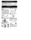
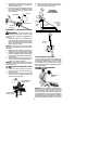
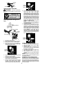
1. Remove wing nut from shield.
2. Insert bracket into slot on shield.
3. Pivot s hielduntil boltpasses throughhol e
in bracket.
4. Tighten the wing nut securely.
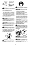
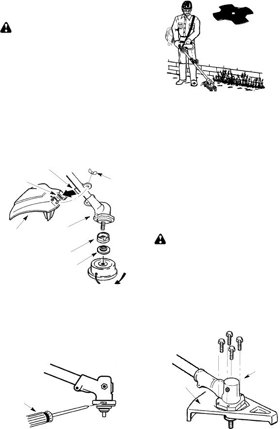
NOTE:
If your unit has a plastic cover over
thethreadson thethreadeds haft,removethe
coveringtoexposethethreads.Beforeinstal-
ling thetrimmerhead,makesure thedustcup
and retaining washer are positioned on the
gearbox as shown below.
Wing Nut
Retaining Washer
Dust Cup
Bracket
Slot
Shield
Gearbox
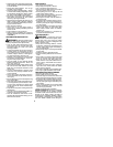
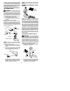
NOTE:
Make sure all parts are properly
installed as shown in the illustration before
installing the trimmer head.
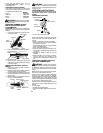
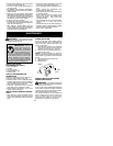
5. Align hole in the dust cup with the hole in
the side of the gearbox by rotating the
dust cup.
6. Insert a small screwdriver into aligned
holes. This will keep the shaft from turn-
ing while tightening trimmer head.
Screwdriver
7. While holding thescrewdriver in position,
thread trimmer head onto the shaft in the
direction shown on the decal (counter-
clockwise). Tighten until secure.
NOTE:
The retaining washer must be posi-
tioned with the raised section facing toward the
gearbox.
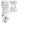
ASSEMBLY INFORMATION -- WEED
BLADE
WEED
BLADE
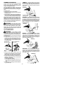
NOTE:
Remove the trimmer head and plastic
shield before attaching the metal shield and
in sta lling th e wee d b lad e. To remov e the trim-
mer hea d,align h ole inthedust cupwith thehole
in the side of the gearbox by rota ting the dust
cu p. Ins ert a s mall screwdriver int o aligne d
h ole s. T hiswill keeptheshaf tf ro mturn ingw hile
loose ning the trimmer head. Remove the trim-
mer head by t urning clockwise. Remove the
screwd rive r. To remove the plastic shie ld, l oos-
en an d r emovewing nut. Pivot shield to release
bracket from slot. See INSTALLATION OF
THECUTTINGHEADandATTACHINGTHE
PLASTICSHIELDforillustrations. Besureto
store all parts and instructions for futureuse.
Never use the trimmer head with the metal
blade installed.
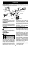
ATTACHING THE METAL SHIELD
W ARNING:
The metal shield must
be properly installed on the tool anytime the
toolis usedwitha blade.Theforwardtipofthe
metal shield helps to reduce the occurrence
ofblade thrustwhichcan causeseriousinjury
such as amputation to the operator or by-
standers. Failure to install the shield in the
position shown can result in serious injury to
theoperator. Thelengthof the shield must be
aligned with the length of the shaft.
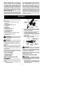
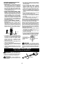
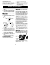
1. Place the metal shield under th e gearbox,
and align the screw holes.
Shield
Gearbox
2. Insert and thread the 4 mounting screws
through the holes of the gearbox and the
metal shield. Tightenevenly andsecure-
ly with the hex wrench provided.