


4
otherwise healthy people. If symptoms occur
such as numbness, pain, loss of strength,
change in skin color or texture, or loss of fee ling
in the fingers, hands, or joints, discontinue the
use of this tool and seek medical attention. An
anti--vibration system d oes n ot guaran tee th e
avoidance of these problems. Users who oper-
ate p ower to ols on a continual and regula r basis
must monitor closely th eir physical condition
and the condition of this tool.
SPECIAL NOTICE:
This unit is equipped
with a temperaturelimiting muffler and spark
arresting screen which meets the require-
ments ofCalifornia Codes4442and4443. All
U.S. forest land and the states of California,
Idaho, Maine, Minnesota, New Jersey, Ore-
gon, and Washington require by law that
many internal combustion engines be
equippedwithasparkarrestingscreen. Ifyou
operateinalocalewheresuchregulationsex-
ist, youarelegally responsible formaintaining
theoperatingconditionof theseparts. Failure
to do so is a violation of the law. For normal
homeowneruse,themufflerandsparkarrest-
ing screen will not require any service. After
50 hours of use, we recommend that your
mufflerbeserviced o rreplacedbyyour autho-
rized service dealer.
ASSEMBLY
CARTON CONTENTS
Check carton contents against the following
list:
S
Powerhead
S
Lower attachment (with trimmer head
installed)
S
Cupped washer
S
Large nut for installing blades
S
Hex wrench
S
Handlebar
S
Bracket cover
S
Bracket cover screws (2)
S
Metal blade shield
S
Blade shield screws (4)
S
4--point weed blade
S
Plastic shield
S
Wing nut (screwed onto plastic shield)
S
Shoulder strap with warning
S
Container of oil
W ARNING:
Always stopunitanddis-
connect spark plug befor eperforminganyas-
sembly procedures.
W ARNING:
If received assembled,
repeatall steps toensure y ourunit is properly
assembled and all fasteners are secure.
Examine parts for damage. Do not use dam-
aged parts.
NOTE:
If you need assistance or find parts
missing or damaged, call 1-800-554-6723.
It is normal for the fuel filter to rattle in the
empty fuel tank.
Finding fuel or oi l residue onmuffler is normal
due to carburetor adjustments and testing
done by the manufacturer.
TOOLS REQUIRED
S
Hex wrench (provided)
S
Adjustable wrench
S
Phillips screwdriver
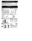
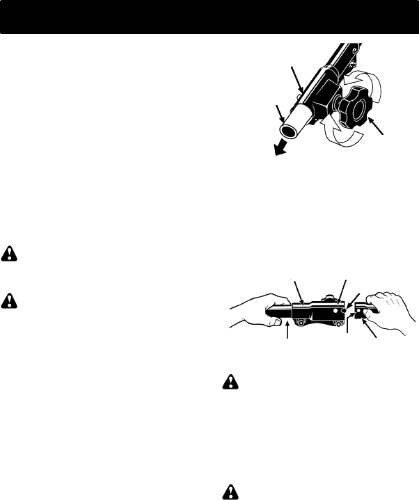
INSTALLING BRUSHCUTTER
ATTACHMENT
CAUTION:
When installing brushcutter at-
tachment, place the unit on a flat surface for
stability.
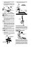
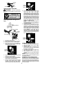
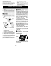
1. Loosen the coupler by turning the knob
counterclockwise.
Coupler
Knob
LOOSEN
TIGHTEN
Shipping
protector
2. Remove shipping protectorfromcoupler.
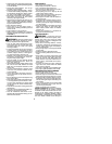
3. Remove the shaft cap from the brushcutter
attachme n t (if presen t ).
4. Position locking/release buttonofattach-
ment into guide recess of coupler.
5. Pushtheattachmentintothecoupleruntil
the locking/release button snaps into the
primary hole.
6. Before using the unit, tighten the knob se-
cure ly by turn ing clockw is e.
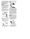
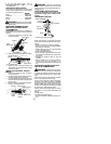
Coupler Primary Hole
Upper
Shaft
Locking/
Release
Button
Lower
Attachment
Guide Recess
W ARNING:
Make sure the locking/
release button is locked in the primary hole
andthe knob is securely tightened beforeop-
eratingthe uni t. All attachmentsaredesigned
to be used in the primary hole.
For optional attachments, see the AS-
SEMBLY section of the applicable attach-
ment instruction manual.
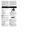
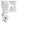
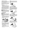
ATTACHING THE HANDLEBAR
DANGER:
To avoid serious injury , th e
barrier p ortion ofthe handlebarmust beinstalled
as shown to provide a barrier between operator
and the spinning blade.
1. Locate the decal on the handlebar. This
decal includes an arrow. Position the
handlebar with the mounting bracket at
the end of the arrow.