


5
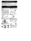
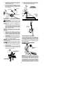
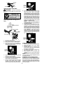
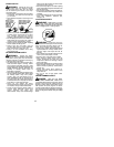
2. Position the bracket cover over the han-
dlebar. Again make sure t hehandlebaris
at the end of the arrow.
3. Insert screws and hand tighten only. Be
sure the handlebar is installed correctly;
then, tighten each screw securely with
the hex wrench.
Screw
Mounting
Bracket
Handlebar
Bracket Cover
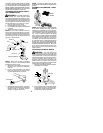
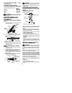
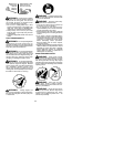
ASSEMBLY OF SHOULDER STRAP
W ARNING:
Proper shoulder strap
and handlebar adjustments must be made
with the engine completely stopped before
using unit.
1. Insert your right arm and head through
the shoulder strap and allow it to rest on
your left shoulder. Make sure the danger
sign is onyour back andthehookis tothe
right side of your waist.
NOTE:
A one-half twist is built in the shoul-
der strap to allow the strap to rest flat on the
shoulder.
2. Adjust the strap, allowing the hook to be
about 6 inches (15 cm) below the waist.
3. Fasten the strap ho ok to the clamp located
between the trigger handle and the handle-
bar clamp base and lift the tool to the oper-
ating position.
4. Try on shoulder strap and adjust for fit
and balancebefore startingthe engineor
beginning a cutting operation.
NOTE:
It may be necessary to relocate the
shoulder strap clamp on the shaft for proper
balancing of unit.
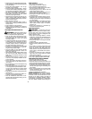
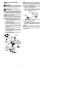
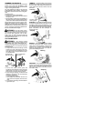
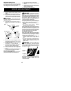
TO RELOCATE SHOULDER STRAP
CLAMP:
1. Loosen and remove both clamp screws.
2. Place the upper shoulder strap clamp
over the shaft.
3. Position the lower shoulder strap clamp
under the shaft and align the upper and
lower clamp screw holes.
Upper Shoulder
Strap Clamp
Screws
Lower Shoulder
Strap Clamp
4. Insert two screws into the screw holes.
5. Secure shoulder strap clamp by tighten-
ing screws with a hex wrench.
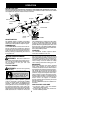
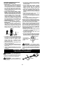
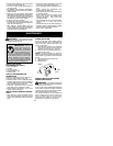
30 inches
(76 cm)
HARNESS
ADJUSTMENT
FOR BALANCE
4 -- 12 inches
(10 -- 30 cm)
above
ground
6 inches
(15 cm)
below
waist
30 inches
(76 cm)
CONFIGURINGYOUR UNIT
You can configure your unit u sing acuttinghead
for grass and light weeds, or a weed blade for
cutting grass, weeds, and brush up to 1/2 inch
(1 cm) in diameter . To assemble your unit, go to
the section for the desired configuration and fo l-
lo w the inst ructions.
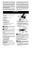
ASSEMBLY INFORMATION --
TRIMMER HEAD
TRIMMER
HEAD
NOTE:
Remove theblade a ndmetal shield be-
fore attaching the plastic shield a nd trimmer
he ad. To remov e blade, align hole in the dust
cup with theholein theside ofthe gearboxby
rotating the blade. Insert a small screwdriver
intoaligned hol es. This willkeeptheshaftfro m
turning while loosening the blade nut. Remove
blade nu t by turning clockwise. Re move the