


24
SERVICE AND ADJUSTMENTS
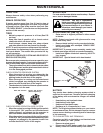
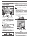
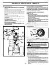
TO REMOVE WHEEL FOR REPAIRS
(See Fig. 35)
• Block up axle securely.
• Remove axle cover, retaining ring and washers to
allow wheel removal (rear wheel contains a square
key - Do not lose).
• Repair tire and reassemble.
• On rear wheels only: align grooves in rear wheel
hub and axle. Insert square key.
• Replace washers and snap retaining ring securely
in axle groove.
• Replace axle cover.
NOTE: To seal tire punctures and prevent flat tires due
to slow leaks, tire sealant may be purchased from your
local parts dealer. Tire sealant also prevents tire dry
rot and corrosion.
FIG. 35
RE TAIN ING
RING
WASH ERS
SQUARE KEY (REAR
WHEEL ONLY)
AXLE COVER
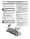
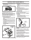
TO START ENGINE WITH A WEAK BATTERY
(See Fig. 36)
WARNING: Lead-acid batteries gen-
er ate ex plo sive gases. Keep sparks,
flame and smoking ma te ri als away from
bat ter ies. Always wear eye pro tec tion
when around batteries.
If your battery is too weak to start the engine, it should
be recharged. (See "BATTERY" in the MAINTENANCE
sec tion of this man u al).
If “jumper ca bles” are used for emer gen cy starting,
follow this pro ce dure:
IMPORTANT: YOUR TRACTOR IS EQUIPPED WITH A 12
VOLT SYSTEM. THE OTHER VEHICLE MUST ALSO BE A 12
VOLT SYSTEM. DO NOT USE YOUR TRACTOR BATTERY TO
START OTHER VEHICLES.
TO ATTACH JUMPER CABLES -
• Connect one end of the RED cable to the POSITIVE
(+) terminal of each battery(A-B), taking care not
to short against tractor chassis.
• Connect one end of the BLACK ca ble to the NEGA-
TIVE (-) terminal (C) of fully charged battery.
• Connect the other end of the BLACK cable (D) to
good chassis ground, away from fuel tank and
bat tery.
electric
02953
A
B
C
D
E
F
G
H
J
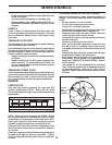
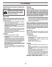
FIG. 34
FRONT WHEEL TOE-IN/CAM BER
Your new tractor front wheel toe-in and camber is set
at the factory and is normal. The front wheel toe-in and
camber are not adjustable. If damage has occurred
to affect the factory set front wheel toe-in or camber,
contact a qualified service center.
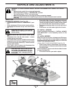
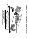
BELT INSTALLATION -
• Install new belt from tractor rear to front, over the
steering plate (H) and above clutch brake pedal
shaft (J).
• Pull belt toward front of tractor and roll belt around
electric clutch and onto engine pulley (G).
• Pull belt toward rear of tractor. Carefully work belt
down around transmission cooling fan and onto
the input pulley (F). Be sure belt is inside the belt
keeper.
• Install belt on centerspan idler (E).
• Install belt through stationary idler (C) and clutch-
ing idler (D).
• Reinstall anti-rotation link (B) on right side of trac-
tor. Tighten securely.
• Reconnect clutch harness (A).
• Make sure belt is in all pulley grooves and in side
all belt guides and keep ers.
• Install mower (See “TO IN STALL MOWER” in this
sec tion of manual).