


www.petsafe.net 9
Over Correction Protection
In the unlikely event that your pet “freezes” in the Static Correction Zone, this feature limits the static correction
duration to a maximum of 30 seconds. While the system locks out further static correction, the warning tone will
continue until the pet leaves the Static Correction Zone.
__________________________________________________
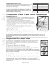
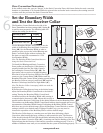
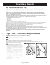
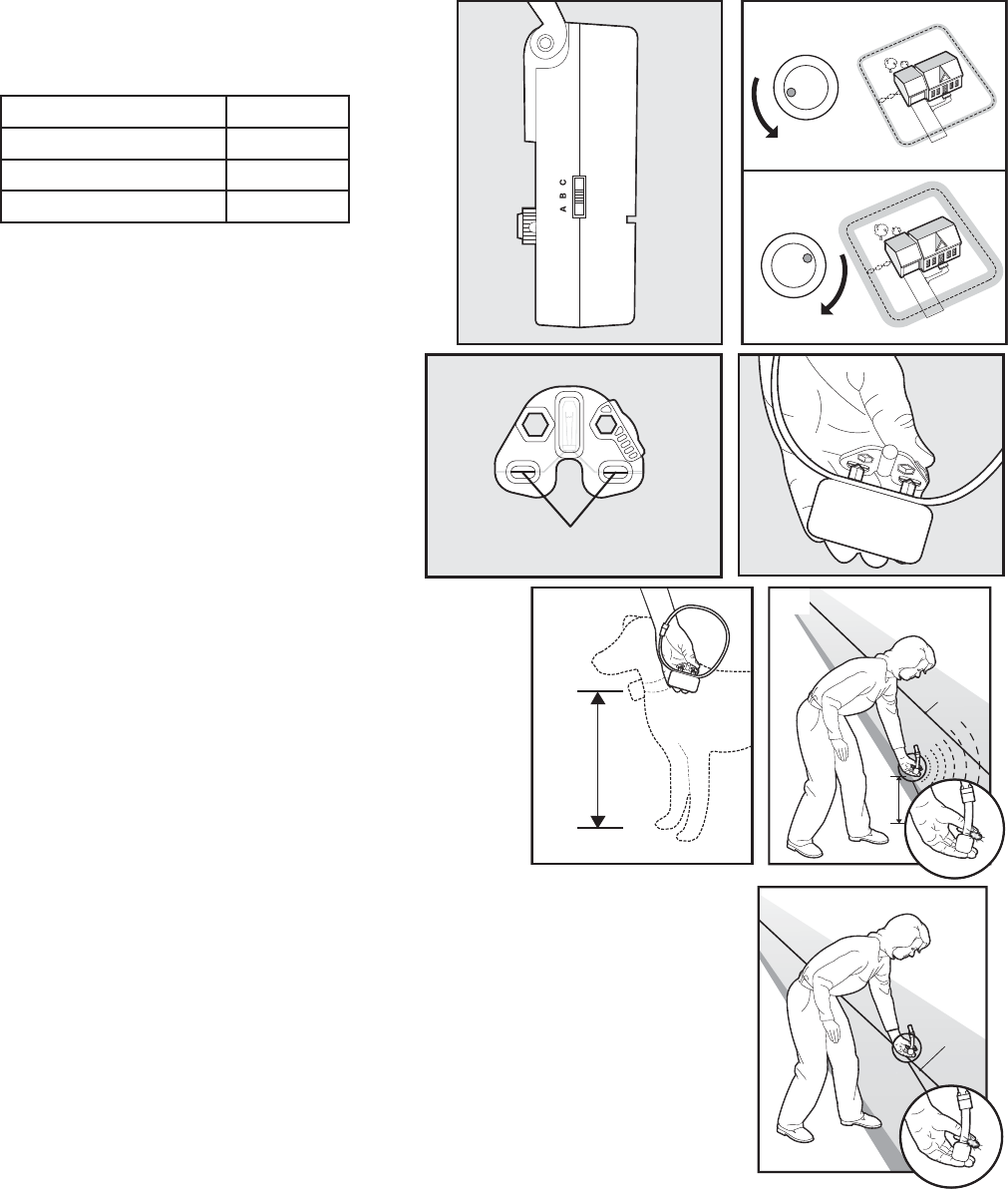
Set the Boundary Width
and Test the Receiver Collar
The Boundary Control Switch on the side of the
Fence Transmitter has three settings (6A). Setting B
is used for most properties. The following table will
indicate the setting you should use.
Amount of Wire Setting
Up to 1300 feet
B
1300-2400
C
Greater than 2400 feet
A
Use the Boundary Width Control knob to set the
width of the Warning Zone and Static Correction
Zone (6B). Set the Boundary Width as wide as
possible to give your pet the widest Warning and
Static Correction Zones without reducing the
6A
5
28
4
10
3
9
1
7
0
6
5
28
4
10
3
9
1
7
0
6
6B
Pet Area too much. We recommend a 12-20
foot Boundary Width.
Note: The Boundary Width Control knob does not
change the Static Correction Level.
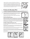
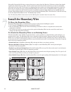
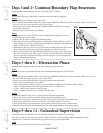
To identify the Warning and Static Correction
Zones, make sure the Receiver Collar battery is
properly installed and the Test Light Contacts
are touching the Contact Points (6C, 6D). For
best results, select a section of straight Boundary
Test Light Contacts
6C
6D
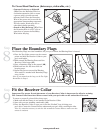
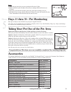
Wire that is at least 50 feet long. Hold the Test Light
contacts to the Contact Points. (6D). Walk toward the
Boundary Wire with Contact Points pointing up and holding
the Receiver Collar at your pet’s neck level (6E) until the
Receiver Collar beeps and the Test Light fl ashes (6F).
Note: The Receiver Collar is waterproof, which can make the
beep hard to hear.
If the Receiver Collar does not beep at the desired range,
adjust the Boundary Width Control knob to the desired
setting. Turning the Boundary Width Control knob
clockwise increases the Boundary Width while turning it
counterclockwise decreases it (6B). Repeat this activity as
6E
Boundary
Wire
6F
needed until the Receiver Collar beeps at the desired distance from the Boundary Wire.
The numbers on the Boundary Width Control knob indicate signal strength and are not
representative of Boundary Width footage. If adjusting the Boundary Width Control
knob does not give the desired range, adjust the Boundary Control Switch to another
setting to achieve your desired range. If using a Double Loop, you may need to
increase the separation of the Boundary Wire to achieve desired range.
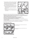
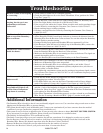
The Receiver Collar beeps as a warning tone and ticks when delivering a Static
Correction. After hearing the beep, continue to walk towards the wire. The Receiver
Collar should tick and the Test Light should fl ash, indicating the Static Correction as
you enter the Static Correction Zone (6G). A warning tone and the fl ashing of the Test
Light indicate that the Receiver Collar and the system are working properly. Test in a
number of different areas until you are satisfi ed that the system is functioning properly.
Boundary
Wire
6G
Step
6